Operation, Phantom power on/off, Pushbutton switches and status leds – Studio Technologies 200 User Manual
Page 14: Conclusion
Model 200 User Guide
Issue 3, August 2004
Studio Technologies, Inc.
Page 15
microphone input. But with a microphone
connected as the input source one should
never use the 0 dB setting. The issue is
that with no gain added to the microphone
input signal, the relative noise floor on the
main and talkback outputs will be much
too high. These outputs are designed for
handling line-level signals, expecting to
receive the output of the microphone
preamplifier. In conclusion, the 0 dB gain
setting doesn’t highlight a problem, but
simply reflects the unit’s gain structure.
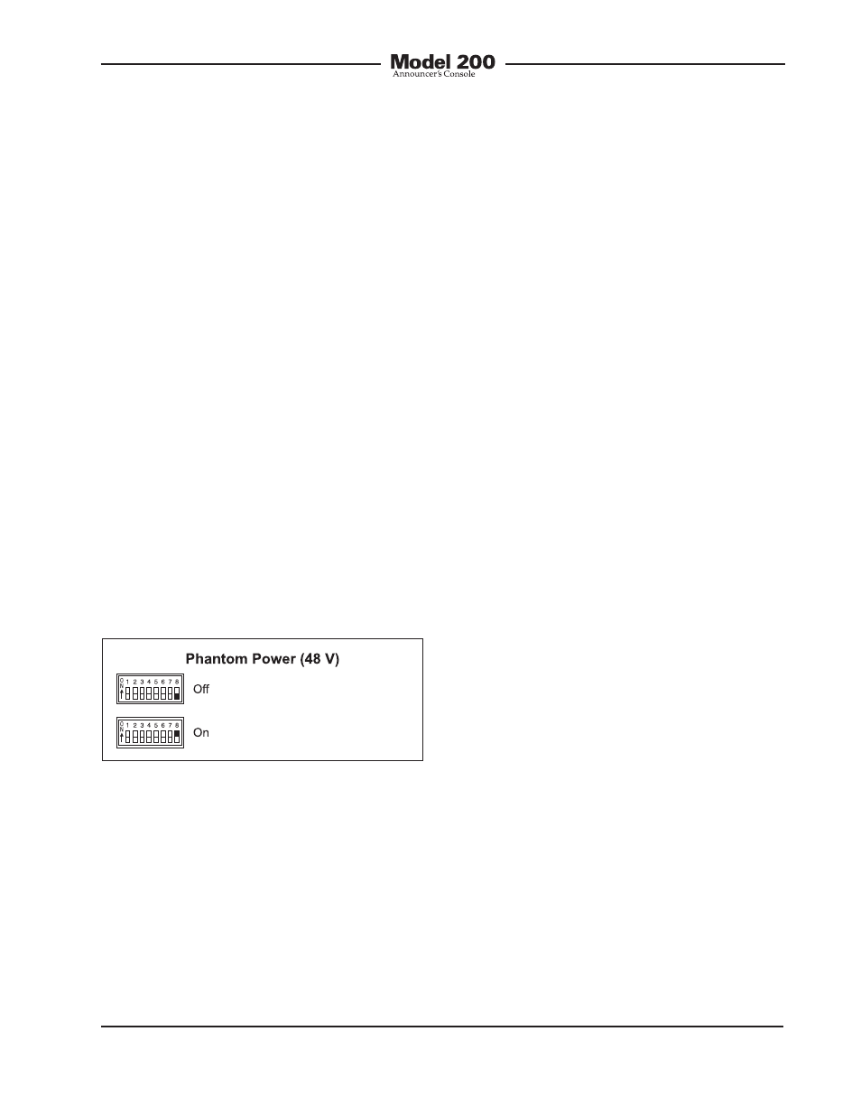
Phantom Power On/Off
Position 8 of the switch assembly controls
the on/off status of the 48 volt phantom
power supply. As expected, placing the
switch to the on position applies phantom
power to the microphone input. By phan-
tom power’s very nature it could be left
applied to the microphone input at all
times. But generally people prefer to
turn it off unless required for a specific
microphone.
Operation
At this point the desired input, output, and
power connections should have been
made. The button labels may have been
revised. Finally, the configuration switches
should have been set. Normal operation
of the Model 200 can now begin. The unit
will begin functioning as soon as a power
source (either the IFB circuit, external 24 volt
DC power source, or both) is connected. It’s
important to highlight the fact that the Model
200 is an active device. Audio signals will
not be present on the main output if correct
power has not been supplied! The micro-
phone does not passively “cut through” to
the main output connector.
Upon power up, only the green LED associ-
ated with the main output button, factory
labeled as COUGH, will be lit. The user
is now presented with two buttons, three
LEDs, and two rotary controls. These are
simple to operate and understand, as will
be described in the following paragraphs.
Pushbutton Switches and
Status LEDs
Two pushbutton switches are used to
control the main and talkback outputs.
The button on the left, factory labeled as
COUGH, provides a push-to-mute function
for the main output. The function is momen-
tary, the output mutes only when the button
is pressed and held. Two LED indicators
are located directly above this button. The
green LED is lit whenever the main output
is active. This could be considered to be an
“on-air” or mic active indicator, or at least
serve as a “careful what you say” warning!
The red LED, located to the left of the green
LED, is lit whenever the main output is not
active.
Conclusion
Once the switches have been set to the
desired configuration, the security plate
should be reattached. The four rubber
bumpers should be hand-tightened only.
No tools should be used.
Figure 5. Phantom power switch settings