Studio Technologies 60A User Manual
Page 12
Issue 1, June 2003
Model 60A/61 User Guide
Page 12
Studio Technologies, Inc.
output is simply to plug a pair of head-
phones into the front panel jack. In other
applications it may be convenient to wire
connector panels located in a control
room, studio, or voice-over booth to the
back-panel headphone jack.
Using a ¼-inch phone plug, the head-
phone output should be wired with tip
as left channel, ring as right channel,
and sleeve as common/shield.
The sonic quality of the headphone out-
puts are such that they are suitable for
use as additional unbalanced line-level
outputs. If it is anticipated that the installa-
tion may benefit from this ability it may be
helpful if the back-panel headphone jack
is wired into jacks on a patch bay. In this
way the headphone output can be rapidly
connected to other pieces of equipment.
Auxiliary Switcher
The hardest part about connecting to the
auxiliary switcher section is deciding how it
is going to be used. It’s really just a set of
¼-inch 3-conductor jacks and three push-
button switches. No active electronics are
associated with the switcher section. It is
configured to handle stereo, balanced
audio signals so that a wide range of
professional and semiprofessional audio
sources can be routed. It’s also perfectly
acceptable to run low-voltage control and
data signals through the auxiliary switcher.
Just ensure that no crosstalk is generated
into the Model 60A’s other audio signals.
Interested parties are encouraged to
review the auxiliary switcher portion of the
Model 60A’s block diagram, included at
the end of this user guide. A quick glance
will be worth many, many words. (Possibly
1000 but we haven’t counted!)
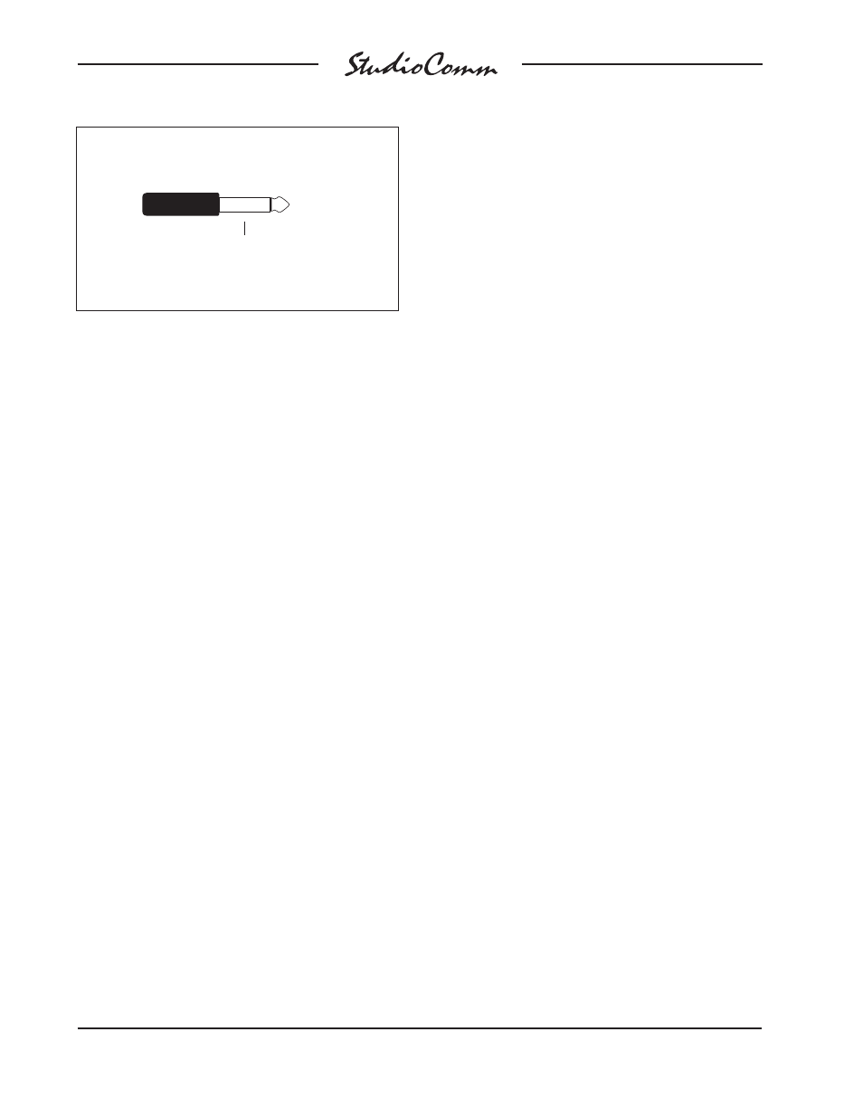
Control Room Mute Connection
Tip: Mute ( + )
(Short to sleeve to
enable mute)
(Switchcraft No. 280, Neutrik NP2C or equivalent)
Sleeve: Shield
to the sleeve lead. Using a ¼-inch phone
plug, connect a normally open contact to
the tip and sleeve. The contact must be
capable of handling a current of 7 milliam-
peres at 15 volts DC.
Dub Output
The Model 60A contains a stereo line-level
output which is intended for connection to
a variety of analog audio devices. The dub
output is electronically balanced and is
capable of driving loads of 600 ohm or
greater. With the input impedance of most
audio devices being 10k ohms or greater,
the dub output can easily drive 10 or more
devices simultaneously.
Prepare the mating connectors (plugs)
so that tip is signal high (+ or hot), ring is
low (– or cold), and sleeve is shield. To
connect to an unbalanced load connect
the tip to high (+ or hot), and both the ring
and sleeve to shield.
Headphone Output
The Model 60A contains headphone
output jacks on both the front and back
panels. For flexibility separate amplifier
circuits support each jack; connecting to
the jack on the front panel doesn’t affect
the jack on the back and vice-versa. The
simplest way of using the headphone