Mounting the model 44, Announcer’s console connections – Studio Technologies 44 User Manual
Page 5
Model 44 User Guide
Issue 2, September 2006
Studio Technologies, Inc.
Page 5
total length of the two cable segments
doesn’t exceed 100 meters.
Mounting the Model 44
Once the desired mounting location has
been selected, the Model 44 will require one
space (1.75 vertical inches) in a standard
19-inch equipment rack. Secure the unit
into the equipment rack using two mounting
screws per side.
Announcer’s Console
Connections
The Model 44 provides support for up to six
announcer’s consoles. In most cases these
will be digital audio-compatible units such
as the Model 212 from Studio Technologies.
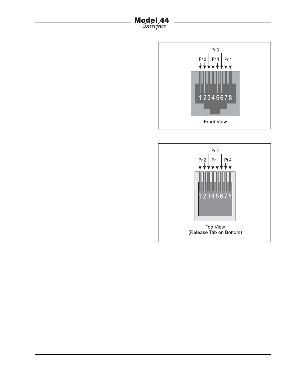
On the Model 44’s back panel are six RJ45
(8-position modular) jacks, one for each
announcer’s console connection. The eight
signal connections in the RJ45 jacks are
organized as four pairs and use the Ether-
net convention: pins 4 and 5 (pair 1), pins 1
and 2 (pair 2), pins 3 and 6 (pair 3), and pins
7 and 8 (pair 4). Pair 4 is used to provide
power to the announcer’s console: +24 volts
DC on pin 7, common on pin 8. Pair 2 (pins
1 and 2) is intended to carry digital audio
signals from the announcer’s console to the
connected equipment. Pair 3 (pins 3 and 6)
is intended to carry digital audio signals from
the connected equipment to the announcer’s
console.
Inside the Model 44 pairs 2 and 3 are routed
directly to six additional RJ45 jacks. Pair 1
(pins 4 and 5) is intended for use in installer-
selected applications. These include sending
or receiving analog audio, digital audio, con-
trol, or “tally” signals. The connections from
pair 1 (pins 4 and 5) on all six announcer’s
console RJ45 jacks are connected inside
the Model 44 to pins on the female 25-pin
D-subminiature connector.
In fixed installations standard CAT5 or
CAT5e Ethernet-style 4-pair cabling can
be used to link the Model 44 with the
announcer’s consoles. The cables should
be implemented with a straight-through
“568A” or “568B” wiring scheme. For re-
mote broadcast or sound reinforcement
applications it may be desirable to use
ruggedized “tactical” cables. In this case
using protected RJ45 plugs, such as the
Neutrik EtherCon, may be appropriate. An
input/output (I/O) panel, separate from the
jacks on the Model 44, should be created
Figure 1. RJ45 Jack (8-Position Modular)
Figure 2. RJ45 Plug (8-Position Modular)