Studio Technologies 43 User Manual
Page 13
Issue 1, July 2004
Model 43 User Guide
Page 14
Studio Technologies, Inc.
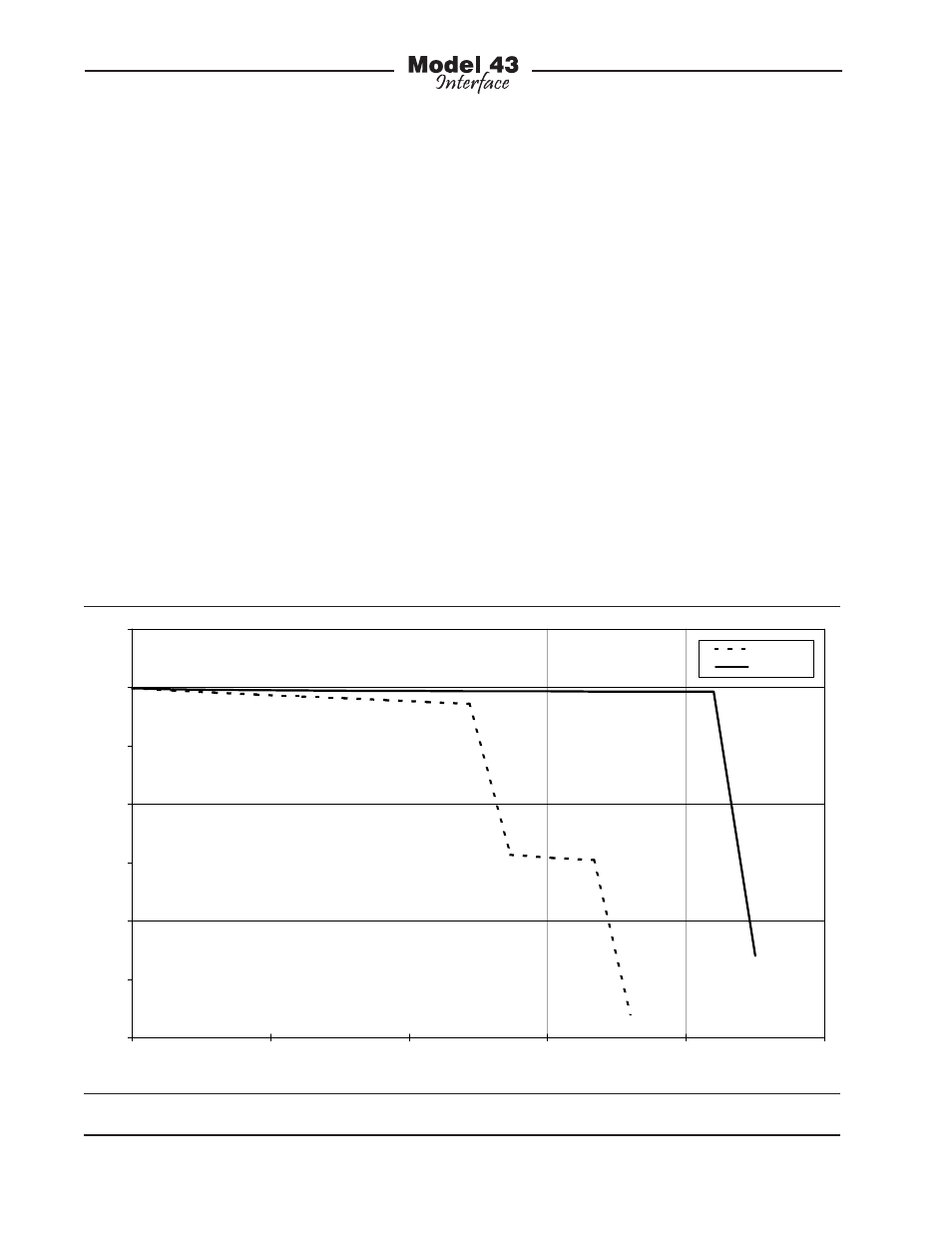
means that the usable power delivered to
the connected device(s) will start to drop
well before the rated output is reached.
This limitation will become significant in
applications that use long cable runs.
As the IFB circuit voltage begins to drop
problems with user device performance
can occur. Contrast this situation with the
performance provided by the Model 43.
The DC voltage supplied by its IFB circuit
won’t “poop out” when loaded over its
0 to 200 milliamperes range. This will al-
low IFB belt pack and announcer’s con-
sole devices to work correctly in many
more applications. Figure 1 shows the IFB
circuit voltage-current curves for the RTS
4000-series and the Model 43 Interface.
The performance differences are quite
interesting.
It’s interesting to note the reason why
typical IFB circuit audio quality is less
than pristine. It’s not hard to notice the
background “hiss” that is always present
on pin 2 (DC with channel 1 audio) of the
interface connector. Technically, it’s white
noise that comes from the adjustable
voltage regulator being used as an “AM”
modulator and current limiter. The noise
is an artifact of the design topology and
simply can’t be overcome. How does
Studio Technologies know this? Because
our first “breadboard” designs used this
method and achieved the same poor re-
sults! Only after the problem came to light
did work on an improved circuit begin.
The results were worth the effort.
Figure 1. IFB Circuit Voltage-Current Curves for RTS 4000-Series and Model 43 Interface
0
5
10
15
20
25
30
35
0
50
100
150
200
250
Current (mA)
V
o
lt
age (
V
)
4010
Model 43