Studio Technologies 5110 V.3.0 User Manual
Page 11
Model 5110 User Guide
Issue 6, October 2012
Studio Technologies, Inc.
Page 11
Model 5110
Mic/Line Input Module
from 0 to 7. (No channel 2 LEDs lit indi-
cates sub-number 0.) The software version
number will display for approximately one
second after the power-up sequence has
completed but before normal operation will
begin. Refer to Figure 6 for a detailed view
of the LEDs and the corresponding soft-
ware version numbering scheme.
Note that while it’s easy to determine
which software version is loaded into
the Model 5110 a trip back to the fac-
tory is required to update it. The 8-bit
microcontroller that provides the unit’s
logic “horsepower” also includes internal
FLASH memory. This nonvolatile memory
is used to store the operating software
(“firmware”). Re-programming this memory
requires using a specialized programming
unit. While not outrageous in price, it still
costs in the range of US$500. The pro-
grammer uses a ribbon cable and socket
to interface with a 6-pin “header” on one
of the Model 5110’s printed circuit board.
And, as you would guess, once connected
reprogramming takes only a matter of sec-
onds. But unfortunately the programmer
is not something that would be found in a
typical “field shop” or repair facility.
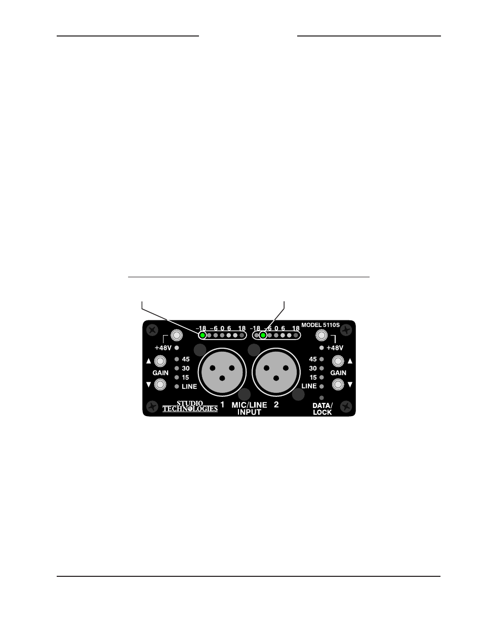
Figure 6. Detail of front panel showing the level meter LEDs
that display the software version. In this example, the software
version is 1.2.
Release Sub-Number
Major Release Number
(
No LED lit indicates .0)
O O O O O O
O O O O O O
1 2 3 4 5 6 7
.1 .2 .3 .4 .5 .6 .7