Studio Technologies 47A User Manual
Page 14
Issue 1, September 2014
Model 47A User Guide
Page 14
Studio Technologies, Inc.
User intercom devices compatible with this
24 kHz “mic kill” signal include RTS TW-Se-
ries beltpacks such as the BP325.
The opto-coupled remote control inputs are
designed for direct connection with 3.3 and
5 volt DC logic signals. An internal 475 ohm
resistor, in series with each opto-coupler’s
photodiode, acts to limit the current flow.
Signals of up to 32 volts DC can be safely
connected as long as the current is limited
to 20 mA maximum. If necessary, an exter-
nal resistor can serve to limit the current.
For example, with a 12 volt DC signal using
a 560 ohm, ¼-watt resistor in series with
the connection would be appropriate. With
a 24 volt DC control signal a series resis-
tor of 1.8 k (1800) ohms is recommended.
No matter the source voltage, for correct
operation a minimum current of 2 mA is
recommended.
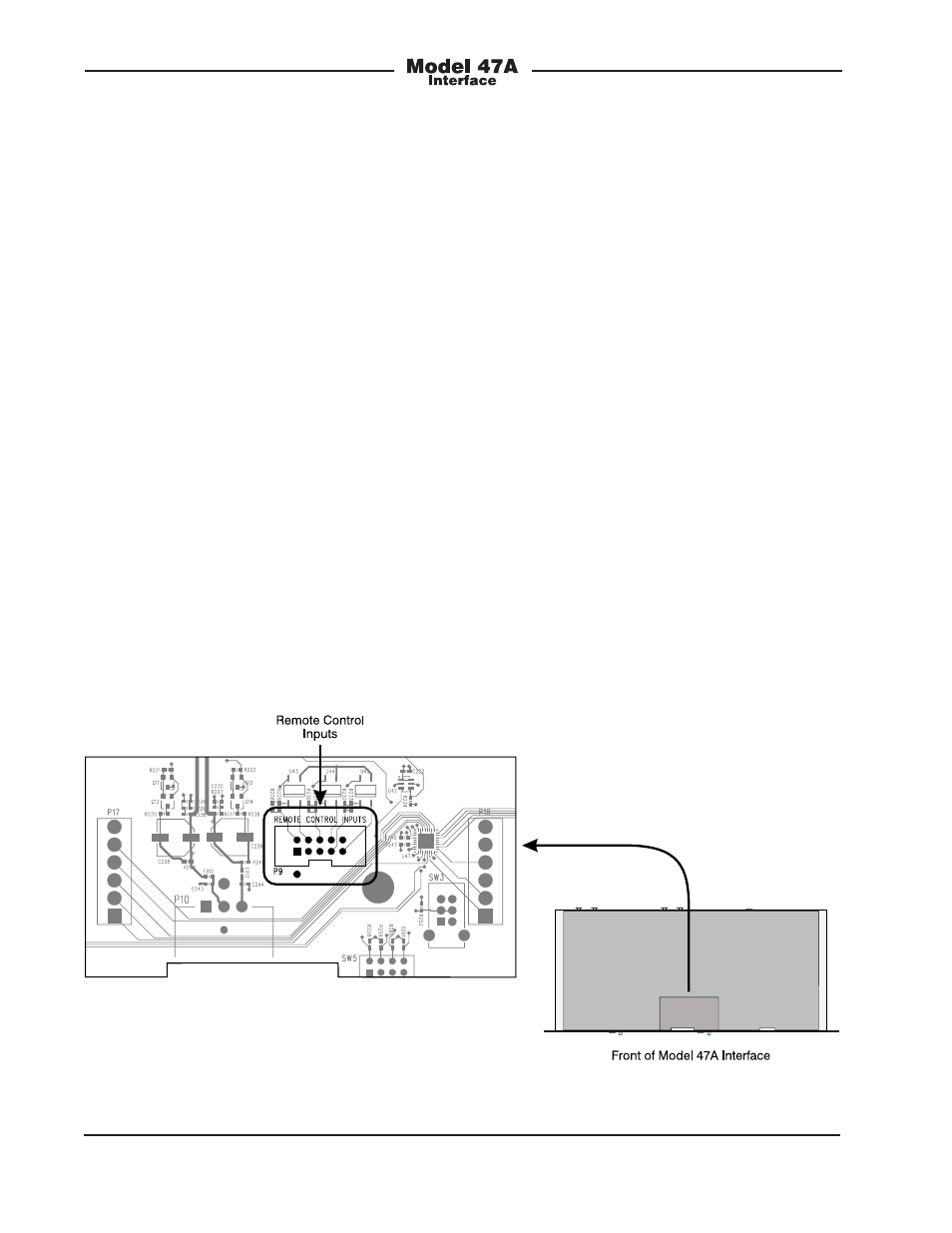
Access to the remote control inputs is pro-
vided by means of a 10-pin male “header”
connector which is located on the Model
47A’s circuit board. Refer to Figure 3 for
a view of the connector’s location. The
“keyed” and “shrouded” header follows a
common industry-standard specification:
two rows of five pins each with 0.1 inch be-
tween rows and pins. The mating connector
is intended to be an insulation-displacement
(IDC) socket connector such as the Tyco
1658620-1. The connector would be “crimp”
terminated onto a piece of 10-conductor flat
ribbon cable. This ribbon cable can safely
exit the Model 47A by laying flat between
the chassis and the cover. The ribbon cable
can then “fan out” to loose wires or, better
yet, be terminated onto another connector
such as a 9-pin D-subminiature type.
A competent technician can easily fabricate
an appropriate remote control input inter-
connect wiring assembly. Starting with a
partially pre-made assembly from Digi-Key
(part number A1AXH-1036G-ND) makes the
task even easier.
Figure 3. Location of 10-pin male header connector on the Model 47A printed circuit board