Configuration, Compatibility with 2-channel intercom systems, Back-panel dip switches – Studio Technologies 45DC User Manual
Page 12: Call light support, Dante configuration
Issue 1, January 2015
Model 45DC User Guide
Page 12
Studio Technologies, Inc.
to connect up to five of them. Wiring from
the Model 45DC intercom interface’s 3-pin
male XLR connectors to the user devices
requires that a 1-to-1, 2-to-2, 3-to-3 wiring
scheme on the mating 3-pin XLR connec-
tors be maintained.
Compatibility with 2-Channel
Intercom Systems
As previously discussed in this guide, the
Model 45DC is designed to support single-
channel party-line intercom circuits and
user devices. It’s possible that applications
that involve 2-channel party-line intercom
circuits and user devices (typically associ-
ated with the RTS TW-series of products)
can also be supported. These circuits and
devices typically utilize common on pin 1,
28 to 32 volts DC and channel 1 audio on
pin 2, and channel 2 audio on pin 3. When
connected to a Model 45DC only channel
2 will be active; channel 1 would not be
utilized. A better means to support these
2-channel circuits and devices is to use the
Studio Technologies Model 45DR Interface.
This unit, the “cousin” of the Model 45DC,
is optimized for 2-channel party-line inter-
com applications. Rather than providing
two single-channel interfaces the Model
45DR provides one 2-channel interface.
Detailed information about the Model 45DR
is available on the Studio Technologies, Inc.
website (www.studio-tech.com).
Configuration
Back-Panel DIP Switches
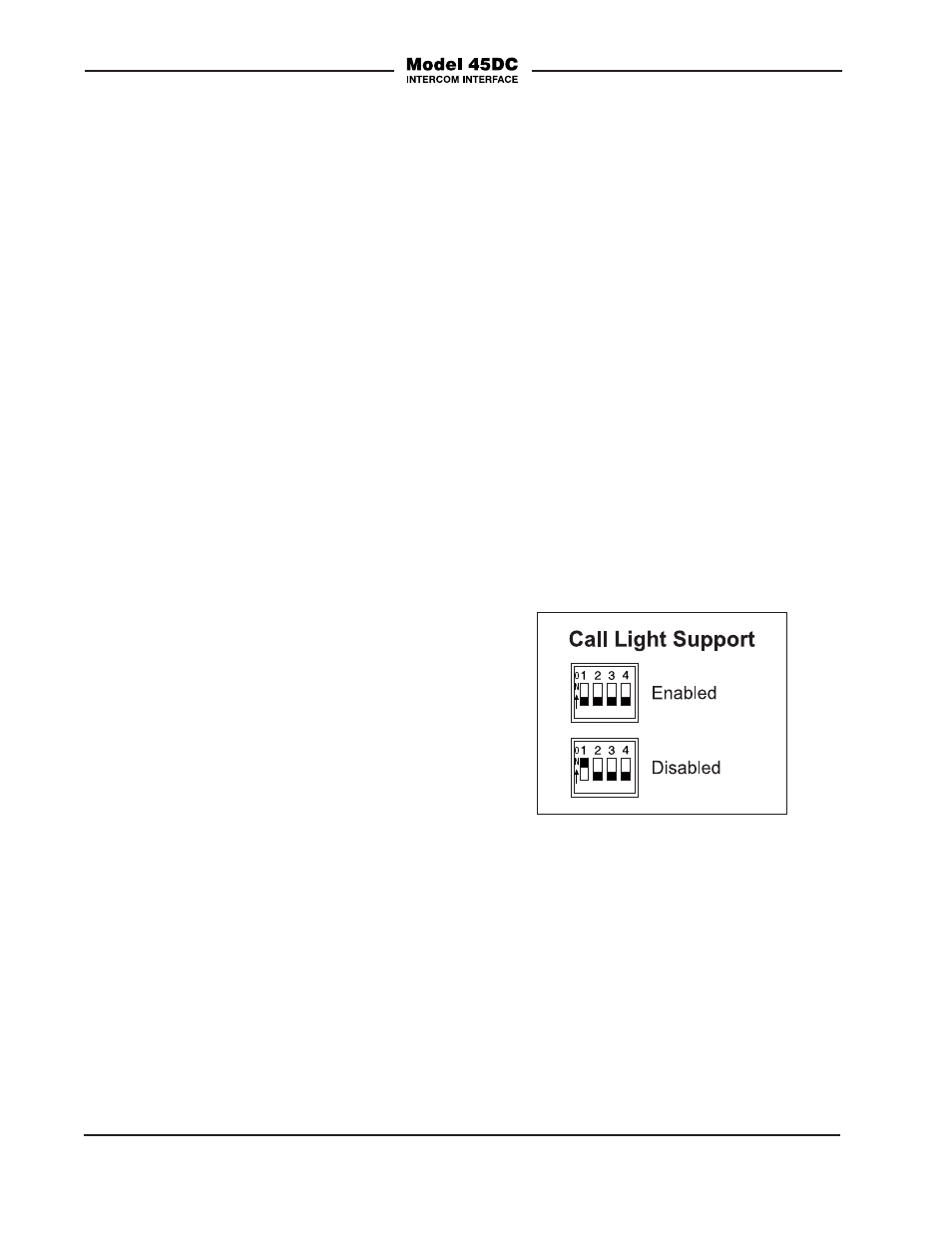
A 4-position DIP switch assembly, labeled
Configuration, is located on the Model
45DC’s back panel. Switch 1 allows the
Model 45DC’s call light support function to
be disabled. Switches 2-4 are not currently
utilized and have no impact on Model
45DC operation.
Call Light Support
When switch 1 is in its off (down) position
the call light support function is enabled.
When switch 1 is in its on (up) position
the function is disabled. For most ap-
plications the call light support function
should remain enabled. Only special
circumstances would merit disabling the
function. Note that the call light function
between user devices connected to the
same Model 45DC interface will always
be active. Disabling the Model 45DC’s call
light support function only impacts the call
function that’s sent and received by way of
the Dante audio connections.
Dante Configuration
To integrate the Model 45DC into an appli-
cation a number of Dante-related param-
eters can be configured. At a minimum,
the audio input (receiver) and audio out-
put (transmitter) channels must be routed.
The configuration settings will be stored
in non-volatile memory within the Model
45DC’s circuitry. The Model 45DC uses
the Ultimo 2-input/2-output integrated
Figure 3. Call light support configuration switch