SP Controls AmpLINC System User Manual
Page 10
10
3.2.1 Node Input Connections
The AmpLINC system utilizes Cat5 to send power as well as a ste-
reo signal to each node on the line. For the initial connection be-
tween the AmpLINC Hub and an AmpLINC Puck, a Cat5 cable
should connect any port on the Hub with either the left or right
port of the node. The remaining port of the node can be used to
daisy chain it to another node.
Caution: Do not connect the final Puck in a line back to
the AmpLINC Hub. Doing so may damage the Hub.
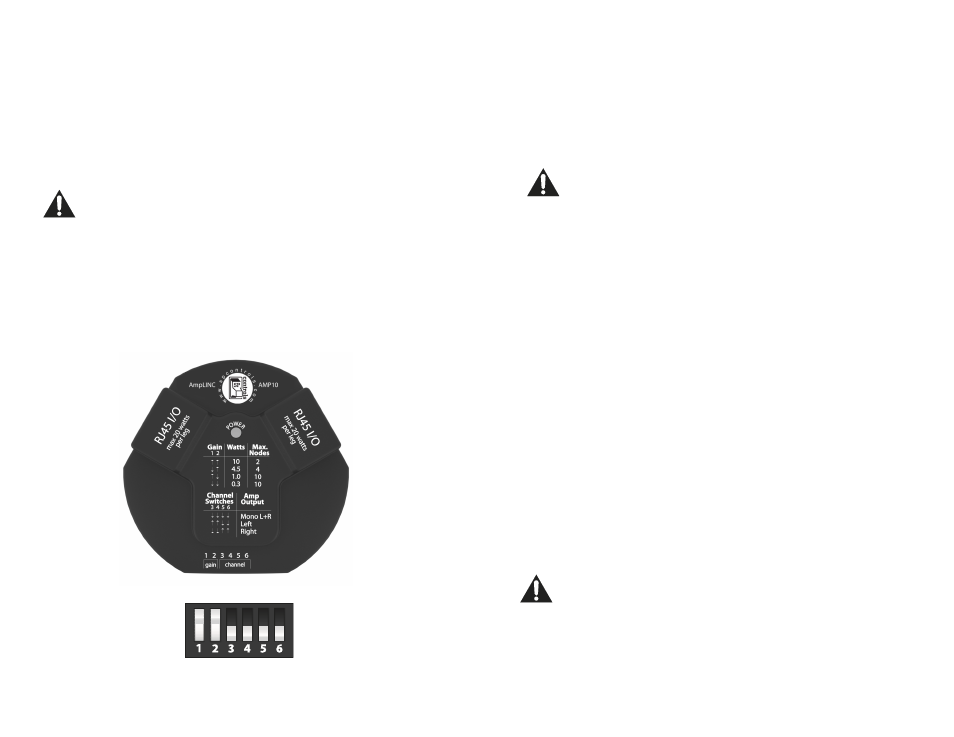
3.2.2 AmpLINC Puck Configuration
The Pucks are configured on an individual basis using the DIP
switches located on the front of the node. This can be done with
a small screwdriver or other tool that will fit into the recessed
switches. The configuration options are found printed on the top
of the Puck
below.
11
Gain Configuration
The gain level on the Puck is adjustable from 0.3W to 10W using
the DIP switches on the front of the unit. Using the table printed
on the top of the node or provided for you on the left, adjust the
first 2 DIP switches to the desired setting.
Note: Each port from the hub is capable of supplying 20W
each. This means that the higher the gain setting, the
fewer units you can daisy chain. Refer to the table below.
Channel Configuration
When the signal is sent down the Cat5 cable from the Hub to the
Pucks, both the left and right channels are sent. This means that
each AmpLINC Puck can be configured to output the left chan-
nel, right channel, or a mono summation. The last 4 switches of
the DIP switch are for selecting the channel.
Refer to the image in section 3.2.2 or the silkscreen of the ampli-
fier node for switch configurations.
Note: Each port from the Hub is capable of supplying up
to 20W each. This means that the higher the gain setting,
the fewer units you can daisy chain. Refer to the table be-
low.
Selected Wattage
# of Units/Port
10W
2
4.5W
4
1.0W
15*
0.3W
50*
*Number reduced to account for power loss over ca-
ble