Capswitcher – Southern States 15.5 kV-38 kV CapSwitcher User Manual
Page 4
Title: Southern States 15.5 kV - 38 kV
CapSwitcher
®
Vertical Interrupter Style Capacitor Switcher
Product Specification
Guide
Page 4 of 8
Publication No.: PSG-809-101714
3.02.02 Additional
The capacitor switcher shall have an endurance life of 10,000 operations.
3.02.03 Source Supply Voltages
Purchaser will supply the following sources for the motor, auxiliary, and
control circuits:
1. Motor
125 VDC; 120 VAC, 60 Hz, 1
2. Control Voltage
48 VDC; 125 VDC; 120 VAC, 60 Hz, 1
3. Auxiliary Voltage
120 VAC, 60 Hz, 1
3.03 Resistors
The capacitor switcher shall be constructed with pre-insertion (closing) resistors
for damping transients caused by switching capacitor banks. The resistor
contacts and the main contacts shall make and break in SF
6
gas.
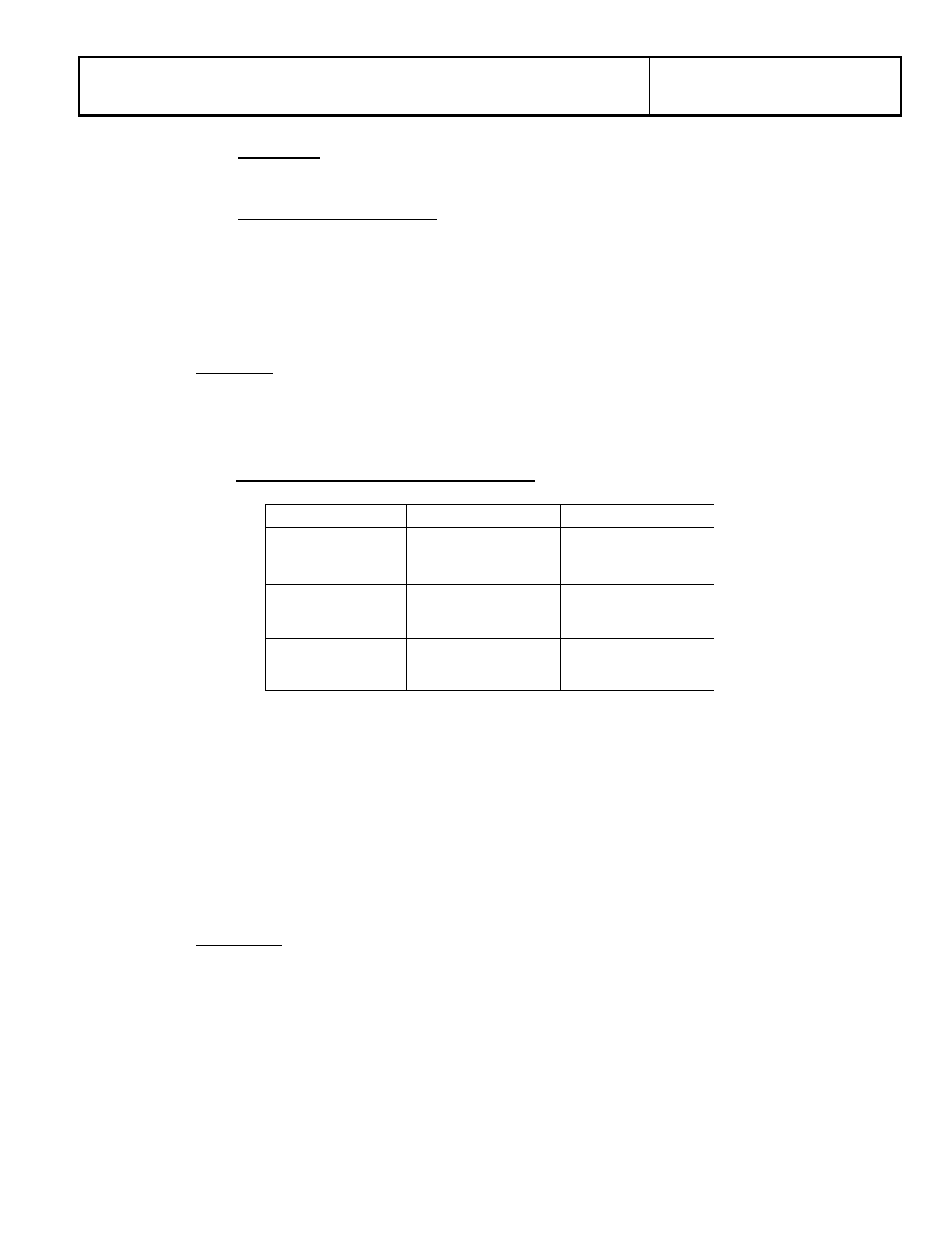
3.03.01 Resistor Values and Selection Chart
15.5 kV
27 kV
38 kV
2 - 6 MVAR
20
3 - 6 MVAR
30
3 - 6 MVAR
90
6.1 - 9 MVAR
10
6.1 - 16 MVAR
20
6.1 - 16 MVAR
30
9.1 - 16 MVAR
6
16.1 - 27 MVAR
12
16.1 - 40 MVAR
12
The resistor must be able to withstand closing into a fault and continue to
perform its specified function without damage. Resistor insertion time shall
be between 5 ms and 12 ms.
The resistor and interrupter must be contained in a common housing. The
interrupter must directly activate the resistor. Designs using separate
housings for the interrupter and resistor (or other transient suppression
device) are not acceptable. Designs that insert the transient suppression
device in air are not acceptable.
3.04 Interrupter
The capacitor switcher shall use SF
6
single gap puffer interrupters. Each
interrupter shall be housed in an insulator that is ANSI 70 gray. Arc assist type
interrupters are not acceptable. Each interrupter shall be provided with an
overpressure relief device and shall be field refillable. Hermetically sealed
interrupters are not acceptable.