SoundTraxx DSD-150/DSX Owners Manual User Manual
Page 23
Digital Sound Decoder Owner's Manual
23
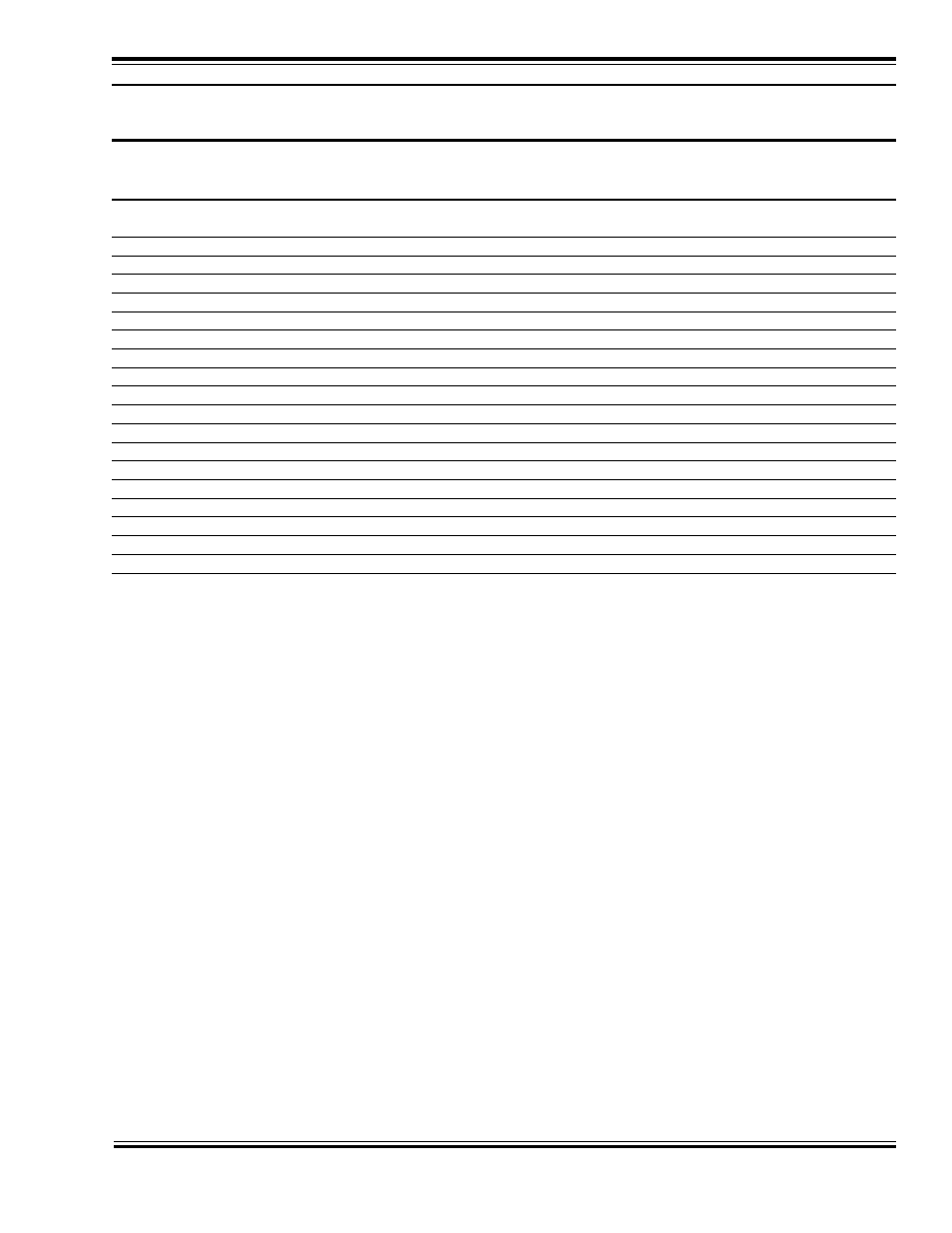
Table B.
Quick-Reference Table for CV29 Values
CV 29
Speed
Use Speed
Address Type
Locomotive
Value
Steps
Tables?
Direction
00 (0x00)
14
No
Primary (CV1)
Normal
16 (0x10)
14
Yes
Primary (CV1)
Normal
32 (0x20)
14
No
Extended (CV17:18)
Normal
48 (0x30)
14
Yes
Extended (CV17:18)
Normal
02 (0x02)
28,128
No
Primary (CV1)
Normal
18 (0x12)
28,128
Yes
Primary (CV1)
Normal
34 (0x22)
28,128
No
Extended (CV17:18)
Normal
50 (0x32)
28,128
Yes
Extended (CV17:18)
Normal
01 (0x01)
14
No
Primary (CV1)
Reversed
17 (0x11)
14
Yes
Primary (CV1)
Reversed
33 (0x21)
14
No
Extended (CV17:18)
Reversed
49 (0x31)
14
Yes
Extended (CV17:18)
Reversed
03 (0x03)
28,128
No
Primary (CV1)
Reversed
19 (0x13)
28,128
Yes
Primary (CV1)
Reversed
35 (0x23)
28,128
No
Extended (CV17:18)
Reversed
51 (0x33)
28,128
Yes
Extended (CV17:18)
Reversed
Configuring the Throttle
There are eight CVs that characterize the DSD’s throttle response and 28 more use to create a custom speed table:
CV 2, VStart
CV 3, Acceleration Rate
CV 4, Braking Rate
CV 9, Motor PWM period
CV 25, Speed Table Select
CV 29, Configuration Data
CV 66, Forward Trim
CV 95, Reverse Trim
CV 67-94, Loadable Speed Table
This may sound like a lot of CVs but don’t worry; it’s not necessary to change all of them if you don’t want to.
Speed Step Mode Selection
As it is a digital system, the DSD splits the throttle voltage over its minimum and maximum range into discrete
speed
steps. The DSD can be configured so there are 14, 28 or 128 individual speed steps. The largest number of steps will
give the smoothest throttle response. Beware that not all DCC systems have the ability to control 28 or 128 speed
steps and your choice will depend upon the capabilities of your command station. The DSD’s speed step mode is
selected by CV 29. Refer to the previous section Configuring the Decoder or the DSD Technical Reference to
determine the correct value for CV 29.
Set the Start Voltage
The DSD provides CV 2, Vstart, to set a starting voltage that is applied to the motor at speed step 1 and is used to
compensate for inefficiencies in the locomotive’s motor and driveline. CV 2 may be programmed with any value
between 0 and 255 (0xFF) with each step in value being about 0.5% of the maximum available motor voltage. To