Step 7. install the exhaust cam – SoundTraxx DSD-150/DSX Owners Manual User Manual
Page 12
12
Digital Sound Decoder Owner's Manual
larger, 2.5mm microbulbs, P.N. 810024, a #41 twist drill works well.
Test fit the microbulb for adequate hole clearance and enlarge the hole if necessary. Next, paint the headlight
castings’ reflector surface with white or silver paint and allow to dry.
Install the light bulbs and secure in place using tape or a flexible glue that does not bond well to glass such as white
glue, rubber cement or RTV. Epoxy or ACC glues will make bulb replacement very difficult and are not recom-
mended.
As a final touch, install a lens using white glue to hold it in place. You may wish to use a commercially available lens
such as those offered by MV Lenses or make your own. A lens can be easily fabricated from a sheet of clear styrene
or alternatively, molded from a drop of clear epoxy that is allowed to flatten and harden on a non-
stick surface.
Firebox Lights
The firebox lights should first be colored with a THIN coat of orange paint followed with a few streaks of red and
yellow. Testors makes a variety of transparent candy enamels for automobile modelers that work well for this pur-
pose. Alternatively, you can use red or orange LEDs in which case painting is unnecessary.
The firebox light should be mounted between the locomotive frame rails in the general vicinity of the ash pan. The
idea is that the bulb is never directly visible but rather casts a gentle glow onto the ground below. The bulb may be
held in place with tape or silicone RTV.
If you are using the Intelligent Firebox Flicker effect, you may wish to modify the locomotive’s firebox door so it is
slightly open and then mount the bulb directly behind it. In this manner, when Fireman Fred puts a few scoops of coal
into the fire, the cab will fill with a soft orange glow.
Step 7. Install the Exhaust Cam
(Optional)
If you are intending to synchronize the steam exhaust chuff using a mechanical cam switch, you have a little more
work to do! Otherwise, if you are planning to use the DSD’s Auto-Exhaust feature, you may skip this step.
Throttle Up! offers its P.N. 810038 Exhaust Cam Kit as an easy to install alternative to traditional axle mounted sound
cams. The Exhaust Cam set provides nine different synchronizer disks of varying diameters and configurations.
Installation is straightforward and unlike the traditional sound cam, has the advantage that the drive wheel does not
need to be removed from the axle.
Begin by selecting the synchronizer disk pattern appropriate for your engine:
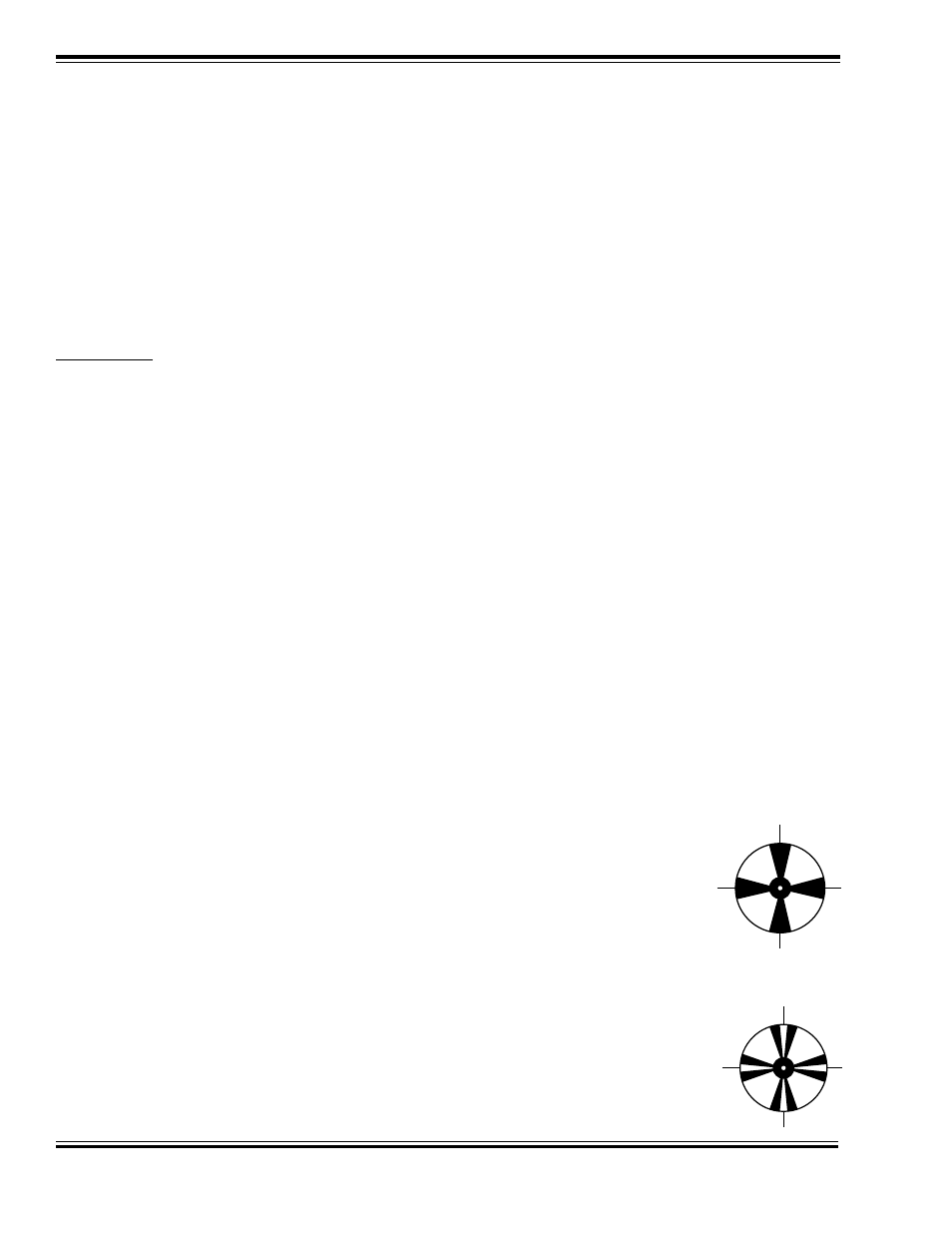
2-Cylinder Steam Locomotives
In all conventional 2-cylinder steam engines, use a synchronizer disk with 4 foil segments. You
can achieve the proper prototypical exhaust chuff timing by aligning the foil strips of the syn-
chronizing disks to the crank pin on the driver wheel.
Articulated Steam Locomotives
Articulated engines come in two flavors, simple and compound. On simple articulated engines,
the cylinders on the front and rear are the same size. On compound engines, one set of cylin-
ders is considerably larger than the second set.
For compound articulated engines, 4 chuffs per driver revolution is correct. Install the same as
for regular locomotives.
For simple articulated engines, a synchronizer disk is available that provides 8 chuffs per driver
revolution.
Geared Locomotives