RLE X-Connector User Manual
Page 2
Input
Output
Branch
1
Branch
2
Sensing Cable
Sensing Cable
SD-Z
EOL
EOL
EOL
0’
100’
150’
250’
300’
350’
400’
500’
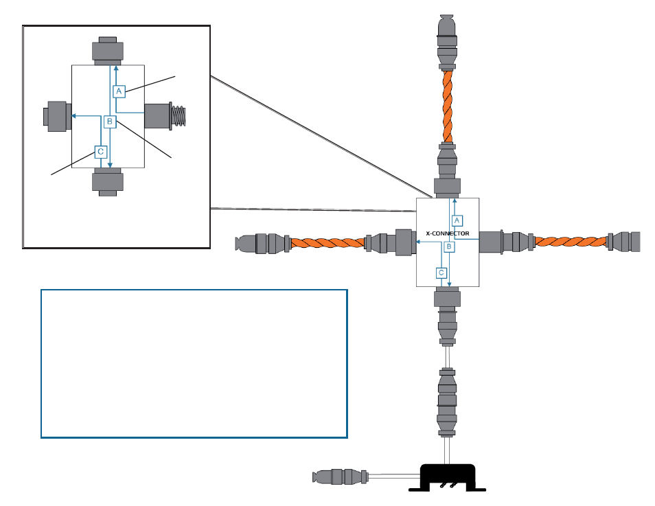
A
simulates
50 feet
(15.24m)
of cable
B
simulates
50 feet
(15.24m)
of cable
C
simulates
50 feet
(15.24m)
of cable
Each X-Connector simulates
150 feet (45.72m) of cable
Sensing Cable
This drawing represents a simulated X-Connector application. For the purposes
of our example, each piece of sensing cable is 100 feet long and the cable’s
resistance is 2.8 ohms/foot. In a distance-read application, an SD-Z simulates
50 feet (15.24m) of cable and each branch of a X-Connector simulates 50 feet
(15.24m) of cable. The diagram shows you how a distance-read system will
calculate the distance at various points along the application.
All of RLE’s orange sensing cable has a resistance of 2.8 ohms/foot. If your
sensing cable’s resistance is 4 ohms/foot, then the X-Connector’s calculations
will be slightly different. At 4 ohms/foot, the X-Connector simulates 35 feet
(10.67m) of cable between branches; 105 feet (32.0m) total per X-Connector.
Please verify the resistance of your leak detection cable before programming
your controller. If you have questions about the resistance of your cable, refer
to the cable’s data sheet.
Simulated
X-Connector Application
To
Controller