Wiring diagram technical data, Fuel pump – REMKO AT 25 User Manual
Page 10
10
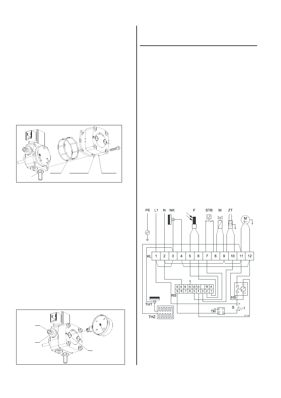
Wiring Diagram
Technical Data
Model
AT 25
Nominal heat output max.
kW
25
Nominal heat output
kW
22,5
Air output
m³/h
1020
Increase of temperature
∆
t
K
54
Fuel
Heating oil EL or Diesel
Fuel consumption, max.
kg/h
2,1
Nozzle (70°W / 80°S)
USG
0,6
Pump pressure approx.
bar
9 - 10
Tank capacity
Ltr.
40
Electrical connection 1~
V
230
Frequency
Hz
50
Rated current max.
A
1,6
Power consumption max.
1)
kW
0,32
Fuse protection (required)
A
10
Sound pressure level L
pA
1m
2)
dB(A)
74
Exhaust connection
∅
mm
150
Length
mm
1250
Width
mm
485
Height
mm
685
Weight
kg
58
1) unit inclusive tank heating
2) noise measuring (when heating) DIN 45635 - 01 KL 3
F = photo cell
HS = auxiliary relay
KL = terminal strip
M = motor
MV = solenoid valve
NK = recool thermostat
RS = relay socket
S = operating switch
STB =
safety temperature
limiter
TH = thermostat socket
THT = thermostat (tank heating)
THZ = tank heating
ZT = ignition transformer
Setting the pump pressure
The pump pressure can only be set if a manometer is
connected to the connection P. The pump pressure is
changed by turning the pressure setting screw A:
clockwise: increase the pressure.
counter clockwise: reduce the pressure.
The required pump pressure is determined according to
the heating capacity (please refer to unit type plate) and
to the nozzle size. The pressure setting screw "A" is to
be secured with the counter nut "B" after having set the
pressure.
Fuel Pump
The standard type of the pump runs in a system of
1 pipe. The required fuel is sucked in through the suction
line "S".
For the first starting and after having emptied the fuel
tank, the fuel system is deaerated through the burner
nozzle.
For this purpose the unit is switched on. After a possible
switch off through failure, the unit is restarted after hav-
ing released the automatic burner relay (take care of
waiting time).
If, after the 3rd start of the unit there is another switch
off through faults, the fuel filters should be checked to
make sure that they are free from pollutions and that
they are tight.
Perfect fuel quality is an absolute necessity for the
lubrication of the pump drive.
Suction of water residues should never take place
and, in the case of setting, suction should not take
place of warping fine dusts (e.g. cement etc.).
Never let the pump run without feeding fuel for a
longer period. Make sure not to leave a unit with
dry run pump unattended for a longer time.
Filter
Gasket
Cover
S
B
A
P