220v lcd lift by draper, Page 4 of 4, Wiring diagram— ir or rf remote control – Draper LCD Lift Video Projector User Manual
Page 4
Page 4 of 4
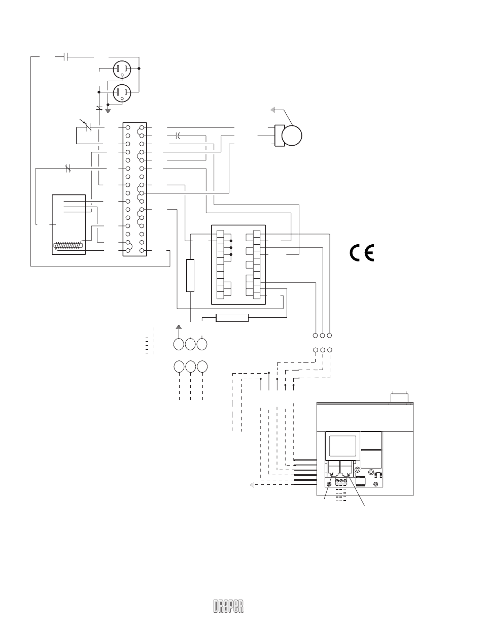
220V LCD Lift by Draper
Wiring Diagram—
IR or RF Remote Control
1 2 3 4 5 6 7 8 9 10
1 2 3 4 5 6 7 8 9 10
Red
Yellow
Black
220 V A
C
Supply
Blac
k
White
White
Black
Black
Black
Black
Black
Black
Black
Black
Black
Black
Yellow
Red
Red
Red
Red
White
White
White
Capacitor
Motor
Black - Down
Red - Up
White - Neutral
Dashed wir
ing b
y
electr
ician
Duple
x Outlet
Switched on only in
the fully do
wn position
Black
White
Y
ello
w/
Green
Receptacle
Limit Switch
LS1 NO
Do
wn T
ra
v
el
Limit Switch
LS2 NC
Up T
ra
v
el
Limit Switch
LS3 NC
Black
Red
A
C
Current
Sensor
1 2 3 4
5
Receptacle Lmt
sw
itch (LS4)
NC
5A
5A
5
6
7
Y
ello
w/
Green
1
2
3
NEU
L1
GND
Wir
ing f
or Remote
Mounting of L
V
C
.
220V A
C
Supply
Neut
Hot
Splice
Red
Bro
wn
Y
ello
w
Blac
k
White
Y
ello
w/
Green
TB1
TB1
TB2
Ey
e P
o
rt
fo
r IR Ey
e
, RF Receiv
er or LED
Switch.
If more than one of these three is
used with one L
V
C-III, a splitter is required.
3 Button W
a
ll Switch
DO
WN - Blac
k
COM - White
UP - Red
Green-Ground
Au
x
P
o
rt
fo
r connecting additional
LV
C-III modules (up to six total-
connect from A
u
x to Ey
e)
Lo
w v
oltage wir
ing b
y
others
www.draperinc.com
(765) 987-7999