Hydraulic block diagram (example), Appendix: 12.5 hydraulic block diagram – Dimplex SI 75ZS User Manual
Page 23
23
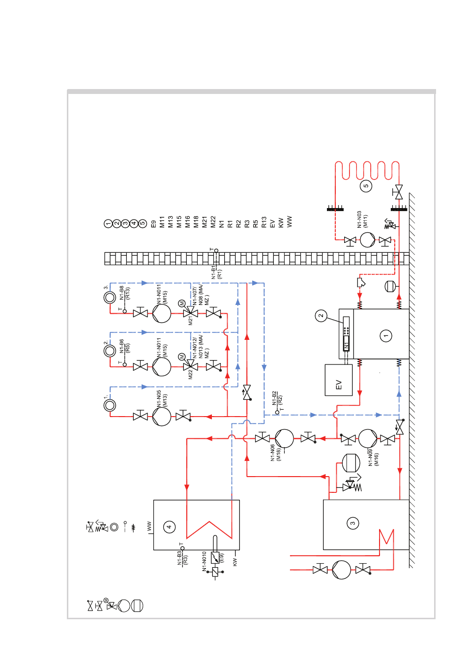
Hydraulic Block Diagram (Example)
APPENDIX: 12.5 HYDRAULIC BLOCK DIAGRAM
Immersion heater
, hot water
Primary circulating pump
Heating circulating pump
Heating circulating pump, heating circuit 2
Suppl. circulating pump
Hot water circulating pump
Mixer
, heating circuit 3
Mixer
, heating circuit 2
Controller unit
External wall sensor
Return sensor
Hot water sensor
Sensor
, heating circuit 2
Sensor
, heating circuit 3
Electric distribution
Cold water
Hot water
Check valve
Shut-of
f valve
Three-way mixing valve
Circulating pump
Expansion vessel
Shut-of
f valve with check valve
Safety valve assembly
Heat consumer
T
emperature sensor
Flexible connecting hose
Brine-to-water heat pump
Heat pump controller
Buf
fer tank
Hot water storage tank
Heat source