Electrical circuit diagram – REMKO KWL 130 H User Manual
Page 29
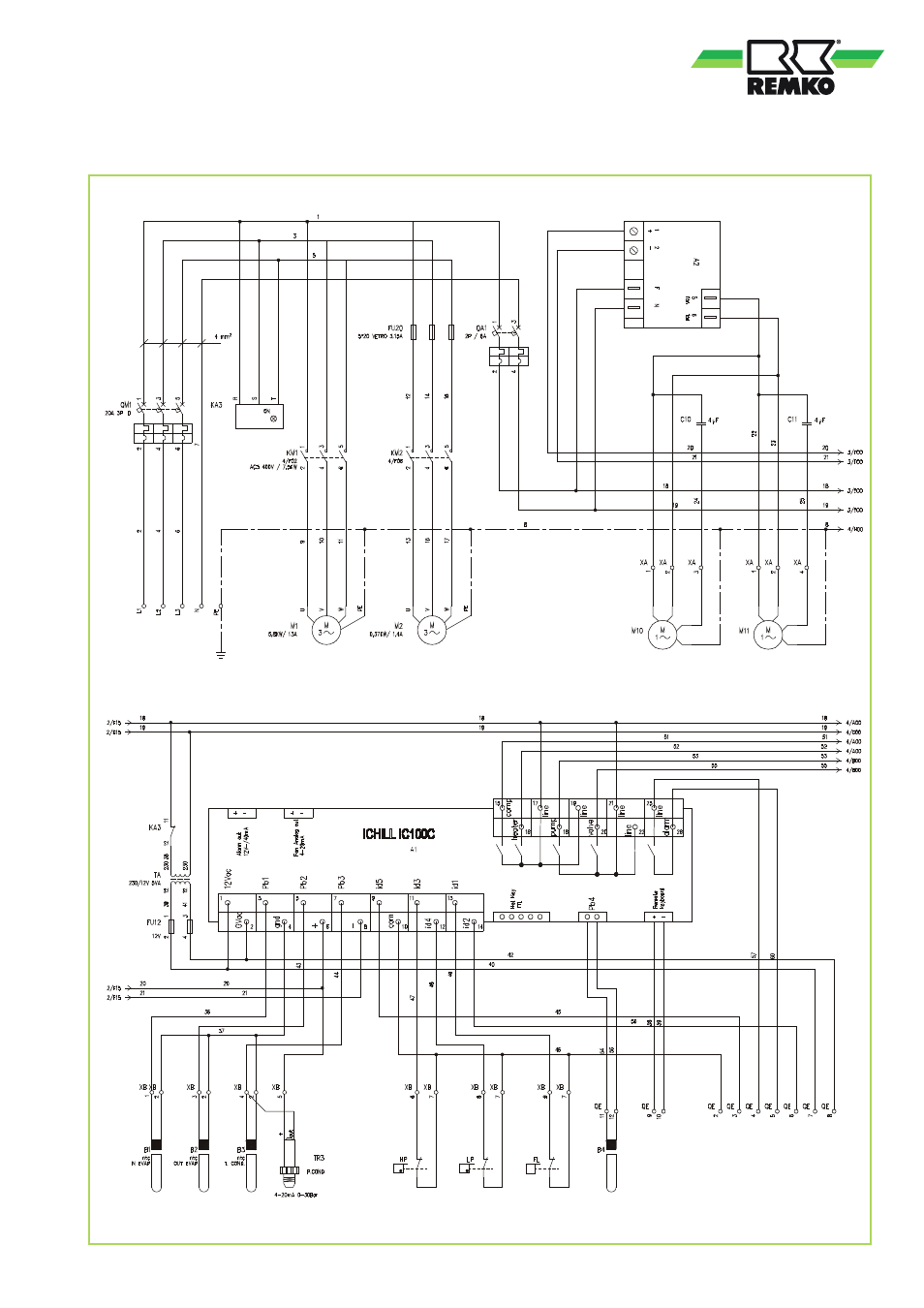
Electrical circuit diagram
KWL 130(H) - 160(H)
KWL 130(H) - 160(H)
2-3 External enabling
4-5 General fault signal
2-6 Cooling-heating switching
7
12V
8
0V
9-10 Cable remote control
Compressor
Probe
Intake
High
pressure
switch
Probe
Outlet
Low pres-
sure switch
Probe
LN-contr.
Diff.press.
switch
Pressure transducer
pressure reg.
(Accessories)
Circulation pump
Fan controller
Condenser
fan 1
Condenser
fan 2
29
This manual is related to the following products: