Reel Mowers F-358 User Manual
Page 6
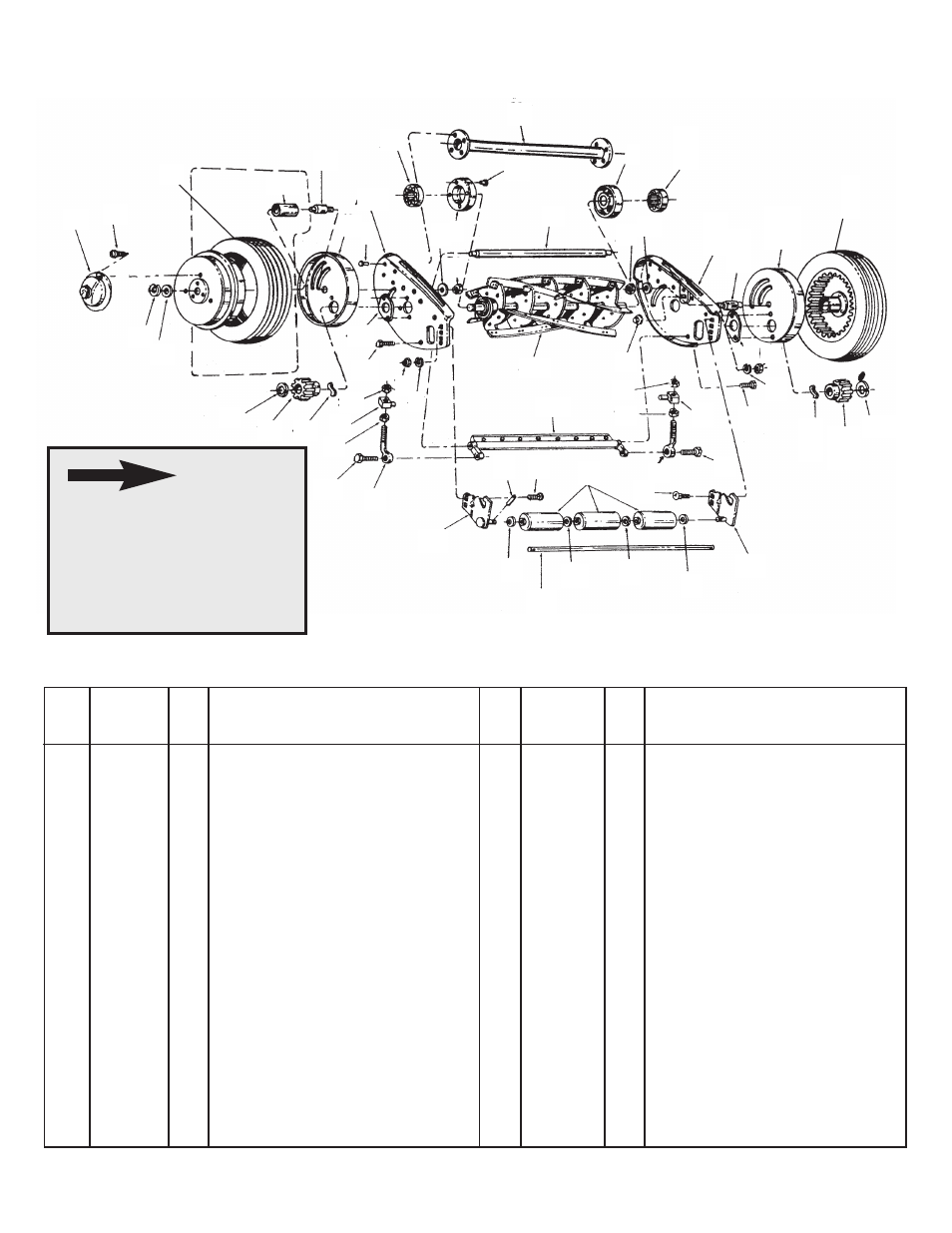
Model 45-0194 21” Single Gang Reel
6
When cutter bar is removed
for sharpening, left hand
pivot bolt (Item 7), must be
turned counterclockwise to
be removed. Right hand
pivot bolt must be turned
clockwise.
NOTE
REPAIR PARTS FOR MODEL NO. 45-0194 21” GANG REEL MOWER
2 2624-110
1
Spacer End Plate
6 44060
8
Rivet 3/16 x 3/8 PLTD
16 1509-086
1
Screw Front L.H. Thd.
19 46324
2
Trunnion for Adjusment Screw
21 0455-000
1
Cutter Screw R.H.
9 1108-95
2
Drive Wheel Assembly
25 1511-029
6
Scr. #10-32 x 1-3/8 Thread Cutting
29 1112-015
1
Spacer Tube Assembly - for 21”
30 44738
2
Nut - 5/16-24 Hex Lock
31 1657-019
2
2 Piece Washer Bushing
32 1118-013
1
Gear Housing R.H.
35 0323-000
1
Pawl
36 0428-000
1
Pinion Gear L.H.
37 1650-001
2
Retaining Ring
40 1650-021
2
Retaining Ring *
41 2674-033
2
Hub Cap
42 43079
2
Carriage Bolt 5/16-18 x 1 *
44 1658-012
3
Roller, each section - 3 required
45 1129-181
1
End Plate R.H. - 21” gang only
47 1631-51
2
Axle
50 44232
2
Bearing
51 1548-007
1
Roller Shaft Pin
53 1629-028
3
Retainer
65 0451-000
2
Cutter Bar Adjusting Bolt
66 0453-000
2
Screw - rear
110 0425-000
1
Pinion Gear R.H.
113 1632-084
1
Roller Shaft - gang and 21” push
114 1129-180
1
End Plate L.H. - 21”
120 1652-052
1
Old Style Bronze Bearing
131 1118-014
1
Gear Housing L.H.
134 1629-009
3
Bearing Retainer
140 2132-045
1
Roller Bracket R.H.
141 2132-044
1
Roller Bracket L.H.
149 3134-024
1
Cutter Bar Assembly - 21”
155 3135-036
1
Reel Assembly - 21”
156
Operators Manual
REF.
PART
QTY.
DESCRIPTION
REF.
PART
QTY.
DESCRIPTION
NO.
NO.
NO.
NO.
* Purchase Common Hardware Locally.
155
40
45
47
9
47
110
35
31
30
2
47
50
114
131
6
31
7
47
120
39
37
40
25
18
9
36
35
20
20
19
66
65
21
38
39
134
134
38
39
16
19
140
43
43
43
113
43
141
51
42
44
42
65
66
20
20
155
149
9
30
16
7