Front i/o plate – Posiflex TX-4200E User Manual
Page 9
Page 9
A: Audio line out port (optional)
B: 1x Antenna port (optional)
C: 1x CR port
D: 1x 2
nd
VGA port (optional)
E: 2x Serial port (RJ-45) COM3 & COM4 port
F: 2x Serial port (RS-232) COM1 & COM2 port
G: 5x USB ports
H: 1x LAN port
I: 1x HDMI port
J: 1x LPT port
K: 1x VGA port (D-sub, 15 PIN)
L: 1x DC IN power connecter
M: 2x USB +12V port
N: 1x Display port
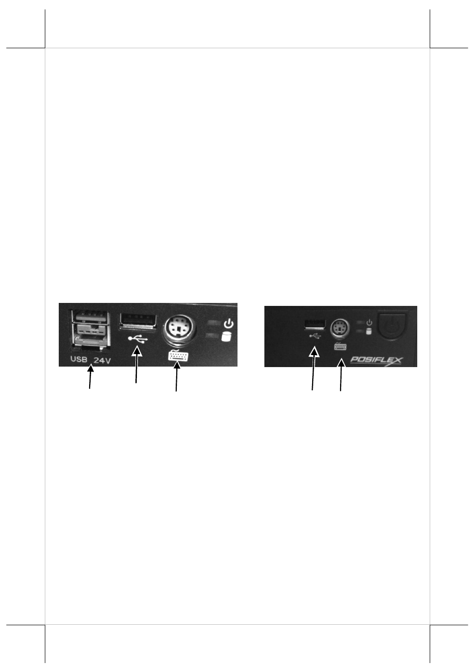
Front I/O Plate
Please hold the base toward yourself for front I/O plate view.
TX-4200E/R TX-4200
M: 1x Power USB +24V
N: 1x USB
O: 1x PS/2
In TX series system, for TX-4200E/4200R/4200, COM1, 2, 3 and 4 can supply
a +5 V DC through system BIOS, for TX-4200E/4200, COM 5 &6 +5V/+12V
are supported by jumper setting, for TX-4200R, COM1/2/3/4 +12V are
supported by jumper setting, for TX-4200, COM1/2/3/4/5/6 +12V are
supported by jumper setting The VGA port can support +12 V power through
system BIOS setting for Posiflex LCD display monitor. 2
nd
VGA port +12V
power is set by jumper. Nevertheless, except Posiflex peripheral device, do
not connect any other device to this port before the power in this port is
disabled.
M
O
N
N
O