Wall mounted e-bus co, Sensor, Setting the address switch – Orion System OE256-05 Wall Mounted v.1 User Manual
Page 5: Technical guide, Addressing & leds on/off
Technical Guide
WALL MOUNTED E-BUS CO
2
SENSOR
5
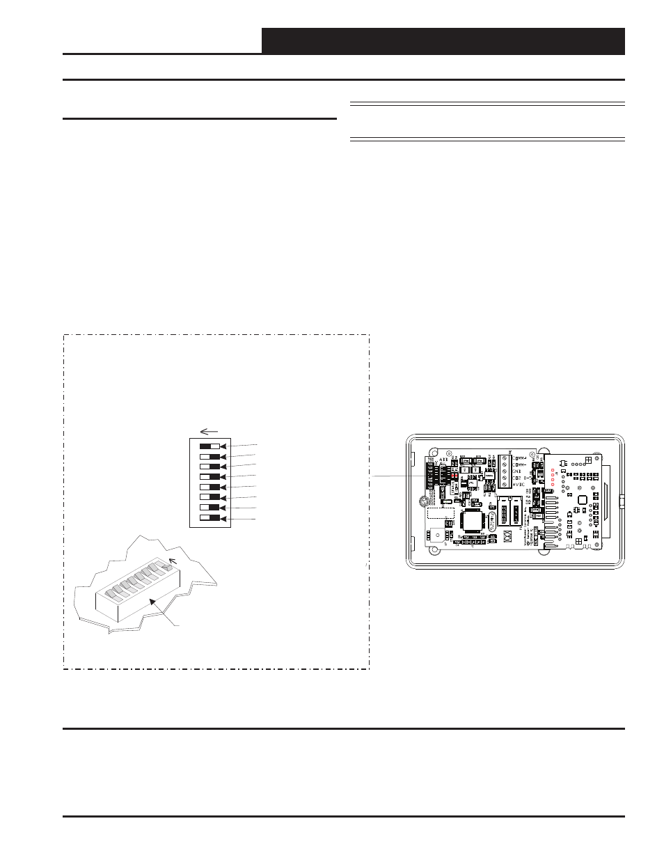
Setting the Address Switch
Addressing & LEDs On/Off
The Wall Mounted E-BUS CO
2
Sensor is equipped with binary dip-
switches. The Address Switch is located on the Sensor’s board and is
only visible by taking the device off the wall and removing the back
cover. See location in Figure 3. The default addresses are as follows:
•
Space or Return CO
2
Sensor = Address 1
• Supply
CO
2
Sensor = Address 2 (Future)
•
Open addresses for Custom Applications = 3-15
•
LEDs On = Dipswitch 8 ON
NOTE: If you forget to set the address, and all dipswitches are
off, the address will default to address 1.
To set the address, follow these instructions:
1. Power up the VCB-X or VCC-X Controller that the Sensor
is plugged into.
2. Set the Dipswitch to the proper setting.
3. The address range can be set from 1 to 15.
4. To verify that the correct address has been entered,
refer to the STATUS LED information on page 6.
The board address is stored in nonvolatile memory. Once the address is
set, the address will be saved after loss of power. See Figure 3 below
for address switch setting information.
Not Used
Not Used
Not Used
LEDs ON
8
4
2
1
Address Switch Shown Is
Set For Address 1
C
Sensor
O
2
Address Switch
NOTE:
Power Up The VCB-X or VCC-X Controller That The C
Sensor Is
Connected To Before Setting the C
Sensor’s Address Switch In
Order For Any Changes To Take Effect. Default Is Address 1. If Using
Only One C
Sensor, There Is No Reason To Change The Address.
O
O
O
2
2
2
ADD
ADD
If Using More Than One C
Sensor,
The Address For Each C
Sensor
Must Be Unique From The Others.
This Feature Is For Future Use.
O
O
2
2
E-BUS C
Sensor with Back Cover Removed
O
2
MI
CR
O
C
H
IP
PI
C
32M
X
440F
51
2H-
80I
/P
T
Figure 3: Setting the Address and LEDs On/Off Option