Olson Technology OTPN-800CH User Manual
Page 7
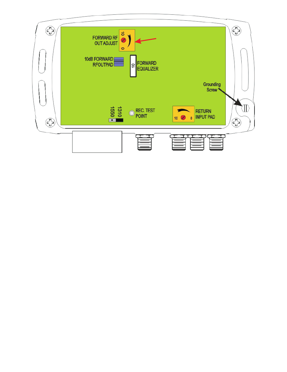
Figure 3 - OTPN-800CH Location of Internal Adjustments
Return Transmitter Setup
External Test Points
The specification for the return band transmitter RF input level is -57dBmV/Hz
(measured at RF Out Port). This value operated the system at the NPR threshold. The
unit has an adjustable attenuator in the return path. A -20dB test point is included in the
return path. The single carrier equivalent of -57dBmV/Hz is +9dBmV per carrier. The
return pad must be adjusted to set the carrier to +9 dBmV after the attenuator. With a test
carrier present at the port (+19dBmV max), measure the level at the return -20dB test
point.Adjust the pad for a -20dB test point reading of -11dBmV return input.
The OTPN-800CH has three external test points. The received “Optical Power” T.P. is
calibrated at 1V per mW @ 1310 nm. Measure with a high impedance voltmeter. This
test point is for monitoring purposes as well as initial setup. Measure the optical power
with a at the time of installation. The reading at 1550nm may be off by 15% even
assuming that the internal jumper has been changed. The jumper is located inside the
unit near the receive level T.P. as shown above. The position closest to the test point is
for 1310nm, and the position farther from the test point is for 1550nm.
The Forward T.P. is -20dB from the receiver RF output. If the RF out is +38 dBmV, then
the T.P. will be about +18dBmV. The Return T.P. is -20dB from the Return transmitter RF
input. Optimal input is +9dBmV (57dBmV/Hz), so the T.P. should read -11dBmV.
Note: This yellow housing
may be removed on
some units.
Note: This yellow housing
may be removed on
some units.