Otor-300 mounting diagram – Olson Technology OTOR-300 User Manual
Page 4
025-000442 REV X2
Page 4
OPTICAL CONNECTORS AND CLEANING
The standard optical connector is an SC/APC. In order to use FC/APC connectors, you must order a conversion kit,
OTLL-SCFCKIT. The standard optical connector location is on the opposite side from the RF connector. The connector
can be moved to the other side by swapping it with a cover plate. Simply remove the cover with removal of the nine
thumb screws.
The fiber ends can be damaged by the insertion of contaminated connectors. Some types of customer damage to
connectors are not covered under warranty. Fiber connectors should never be left uncovered. Prepackaged alcohol
wipes are the most convenient means of cleaning optical connectors. Clean alcohol and lint free wipes or swabs may
also be used.
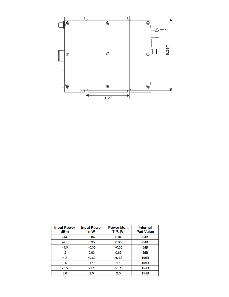
OTOR-300 MOUNTING DIAGRAM
SET-UP PROCEDURE FOR OTOR-300
1. The OTOR-300 is best set up with the use of a digital voltmeter monitoring the optical “Receive Power”. The white
test point on the front of the unit indicates the received optical power at 1V/mW of received optical power. Insert the
positive lead into the white test port and negative lead into the black test port to monitor the received power level.
2. Internal to the unit is a plug-in attenuator that optimizes the performance of the unit based upon the received optical
power. The unit is shippied with a 0 dB attenuator installed, but there are also attenuators for 5, 10, & 15dB installed
in storage sockets internal to the unit. It is recommended that the attenuator listed in the table below be installed based
on the received optical power.To change the internal attenuator, remove the thumb screws from the cover. Then
remove the cover and find the plug-in attenuator and the 5, 10, & 15dB pads per diagram of Figure 1.