Olson Technology LP-DC-X User Manual
Page 7
025-370447 REV X2
Page 7 of 10
INSTALLATION IN CHASSIS
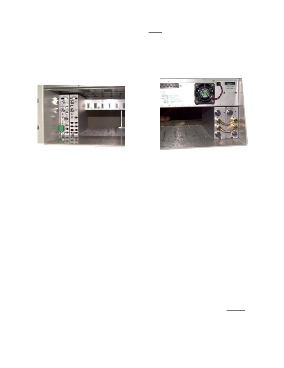
The Laser Plus main chassis should be rack mounted before the modules are installed. This chassis should
never be used as a shipping container. The modules should be gently slid into the chassis. To avoid damage to the
internconnect cables, install the LP-DC’s from the right to the left, as shown below. The LP-DC212 should always
be to the left of the LP-DC234 in which it is connected to. Connect the rear SMB cables.
Note that while the main chassis slots are numbered from the left on the front, they are numbered from the
right on the rear. This could cause confusion relating to which LP-DC212 is connected to which LP-DC234.
REMOVAL FROM CHASSIS
If possible, turn the source laser off. Always put a dust cover over the optical connector. NEVER look
into the end of the fiber.
Disconnect the rear panel SMB cables before removing the modules. Pull each module slightly forward
with the handle until it hits the stop. Lift the front end of the module and remove it. Never use the optical
connector as a handle.
T.P. Volts
Optical Input mW
Optical Input dBm
3.02
3.02
4.8
2.51
2.51
4
2
2
3
1.58
1.58
2
1.26
1.26
1
1
1
0
0.79
0.79
-1
0.63
0.63
-2
0.5
0.5
-3
0.4
0.4
-4
0.32
0.32
-5
0.25
0.25
-6
0.2
0.2
-7
0.16
0.16
-8
0.13
0.13
-9
0.1
0.1
-10
0.08
0.08
-11
0.06
0.06
-12
0.05
0.05
-13
Measure the incoming optical level with a power meter before connecting the fiber. The test point readings
should be recorded for historical reference. The following chart shows the test point readings versus optical input
levels.