Return path spectrum, Overview – Olson Technology LP-DC-X User Manual
Page 5
025-370447 REV X2
Page 5 of 10
5-42MHz
5-42MHz
5-42MHz
5-42MHz
Band 1
Band 2
Band 3
Band 4
FRMUC, RSMII, or
other Olson Technology
Spectrum Multiplier
Laser
Optical Fiber
Olson Technology
LP-DC212
5-42MHz
5-42MHz
Rear Outputs
Full
Spectrum
4.5MHz
Pilot
Photo-
diode
Band 1
Band 3
5-42MHz
5-42MHz
Rear Outputs
Band 2
Band 4
Olson Technology
LP-DC234
Rear
Interconnect
System Overview
Full Spectrum
OVERVIEW
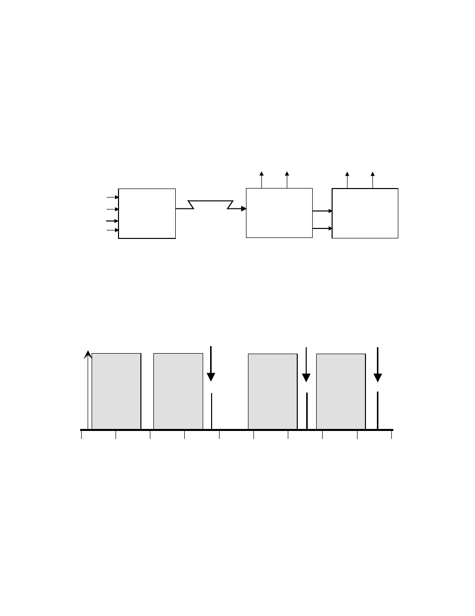
The LP-DC212 and LP-DC234 are the receive sections of a return spectrum multiplier system. They can
double or quadruple the bandwidth of any optical return link. The LP-DC212 by itself can function as a bandwidth
doubler. Both units together will quadruple the return bandwidth. The LP-DC234 requires an LP-DC212 in order
to function. All outputs are phase locked to their inputs, providing transparent operation.
The units plug into an Olson Technology high density Laser Plus chassis. Each unit occupies one slot. The
following diagram shows the overall system.
The next diagram shows the full RF spectrum as it is at both ends of the optical link. Some local oscillator presence
is normal. It will not cause in-band distortion products or degrade NPR.
4.5MHz
Pilot
0
25
50
75
100
125
150
175
200
225
Band 2
51.5-
88.5MHz
Band 3
121.5-
158.5MHz
Band 4
169.5-
206.5MHz
Band 2
L.O.
Band 3
L.O.
Band 4
L.O.
Band 1
5.0-
42.0MHz
Return Path Spectrum