6 operating modes – Northern Airborne Technology 251 User Manual
Page 12
Model 251 Passenger Speaker Amplifier
SM251 Installation and Operation Manual
Section 2 Rev: 1.00
Issue 2
Page 2-4
ENG-FORM: 805-0120.DOT
CONFIDENTIAL AND PROPRIETARY TO NORTHERN AIRBORNE TECHNOLOGY LTD.
2.4.6
Operating Modes
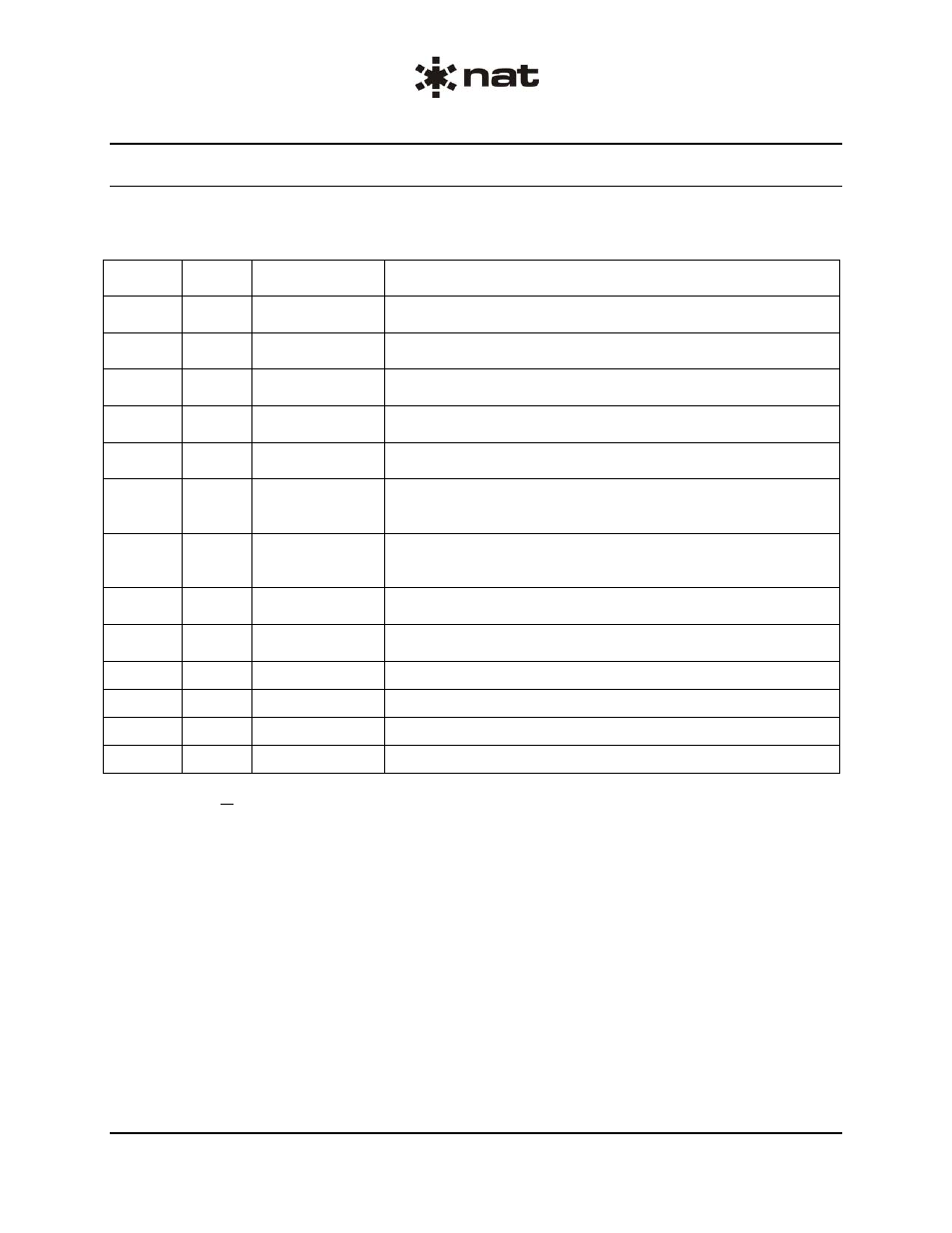
The operating modes of the Model 251 are established when either a ground (low) signal or a 12 to 32
Vdc (high) signal is applied as shown below to the listed connector pin:
Pin No.
Control
Signal
Identification
Function
P50-16
Low
ADF 1 Switch
Connects ADF 1 input audio to left and right speaker and
monitor outputs.
P50-15
Low
ADF 2 Switch
Connects ADF 2 input audio to left and right speaker and
monitor outputs.
P50-14 Low PSC
Switch
Connects Pilot Select Comm (PSC) input audio to left and right
speaker and monitor outputs.
P50-13 Low TV
Switch
Connects TV input audio to left and right speaker and monitor
outputs.
P50-5
Low
Stereo Switch
Connects stereo left and stereo right input audio to left and
right speaker and monitor outputs, respectively.
P50-24 Low PA
Key
Connects PA MIC input audio to PA sidetone, left and right
speaker, and monitor outputs. Opens ADF, PSC, TV, and
stereo input audio circuits.
P50-25
Low
Briefer Switch
Connects briefer input audio to PA sidetone, left and right
speaker, and monitor outputs. Opens ADF, PSC, TV, and
stereo input audio circuits.
P50-31*
No
Smoking
Chime tone to left and right speaker and monitor outputs.
Opens ADF, TV, PSC, and stereo inputs.
P50-32*
Seat
Belt
Chime tone to left and right speaker and monitor outputs.
Opens ADF, TV, PSC, and stereo inputs.
P50-33
Low
Cabin Call
Ringer tone to left and right speaker and monitor outputs.
P50-34
Low
Hook Switch
Disables ringer tone.
P60-8 Low Speaker
Enable
Enables left and right speaker outputs.
P60-3
Low
Speaker Mute
Mutes (lowers volume -6 dB) left and right speaker outputs.
*An application or removal of a High signal at pins P50-31 and P50-32 will provide a chime tone at left
and right speaker outputs regardless of speaker enable status.
Note: P50-XX is a pin on the 37-pin connector, P50
P40-XX is a pin on the 25-pin connector, P40
P60-XX is a pin on the 9-pin connector, P60
The amplifiers are adjusted for acceptable listening output levels into the proper loads with ADF receiver
inputs of 7.75 Vrms, stereo audio inputs of 0.45 Vrms, PSC, TV, and Briefer audio inputs of 1.00 Vrms
and PA MIC input of 0.25 Vrms. With the volume controls set to maximum volume position, these inputs
will provide 7.5 Vrms (28 watts) into 2 ohms at each speaker output. The ADF receiver input levels are
achieved when receivers are set for 100 milliwatts into 600 ohms. If levels are greatly exceeded at any of
the inputs, the audio will become distorted due to peak clipping, and audio bleed-through will occur.
However, the amplifiers will not be damaged.