6 accessories required but not supplied, 7 installation drawings – Northern Airborne Technology 246 User Manual
Page 12
Model 246 Isolation Amplifier
SM246 Installation and Operation Manual
Section 2 Rev: 1.00
Issue 2
Page 2-6
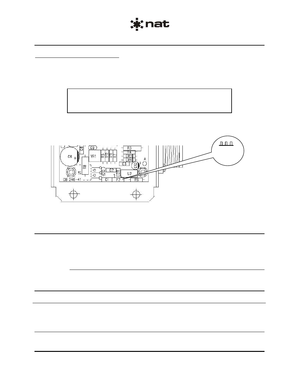
2.5.2.1
Jumper Adjustments
Access to the jumper is by cover removal. Refer to Assembly drawing 246-1 in the SM246 Maintenance
manual. To remove the Model 246 cover, remove the 4 screws in the sides of the unit (do not remove
screws under the base of the unit). Lift the cover to remove. Reinstall the cover by following the same
steps in reverse order. Tighten all screws securely but do not over-tighten.
CAUTION
The Model 246 Series Isolation Amplifier contains static sensitive
devices. Proper ESD handling procedures must be followed to prevent
damage to the unit.
An internal jumper J1 allows the installer to apply a 30 mA microphone bias current to pins A and C. The
microphone may be connected between pins A and B or pins C and B. This makes the Model 246
compatible with the Model 210 Voice Activated Switch.
Note: The Collins unit provides only 5 mA bias current.
When jumper J1 is connected between P2 pins 1 and 2 (closest to connector), the microphone bias current
is enabled. When it is connected between pins 2 and 3 (furthest from the connector), it is disabled.
Pin 3
Pin 2
Pin 1
2.6
Accessories Required But Not Supplied
To complete the installation, a 246-IKC crimp Installation kit, NAT Part # C16S-1-IKC, is required. The kit
consists of the following:
NAT Part #: C16S-1-IKC
Quantity
Description
NAT Part #
1
Circular Socket, Crimp, Bulkhead
20-33-944
2.7
Installation Drawings
DRAWING REV.
DESCRIPTION TYPE
SERIAL
No.
246
246\246\246 1.41
Isolation
Amplifier
Outline
All
246\246\521-0
1.00
Isolation Amplifier
Environmental Qual Form
All
Section 2 ends following the above documents
ENG-FORM: 805-0115.DOT
CONFIDENTIAL AND PROPRIETARY TO NORTHERN AIRBORNE TECHNOLOGY LTD.