2 cautions, 3 cabling and wiring, 4 adjustments – Northern Airborne Technology AA95-766 User Manual
Page 12
AA95-766 Single Channel Audio Controller Manual
SM95-766 Rev. 2.00
2.3.2
Cautions
In all installations, use shielded cable exactly as shown, and ground only as indicated.
Significant problems may result from not following these guidelines.
All audio installations can be seriously degraded by incorrect wiring and shielding, which
may result in abnormal cross-talk, hum and ground-loop noise. Be particularly careful
with all microphone wiring and tie line wiring, as these lines carry the lowest level
signals in the aircraft.
2.3.3
Cabling and Wiring
All unshielded wire shall be selected in accordance with AC43.13-1B Change 1,
Paragraphs 11-76 through 11-78. Wire types should be to MIL-W-22759 as specified in
AC43.13-1B Change 1, Paragraphs 11-85, 11-86, and listed in Table 11-11. For
shielded wire applications, use Tefzel MIL-C-27500 shielded wire with solder sleeves
(for shield terminations) to make the most compact and easily terminated interconnect.
Follow the wiring diagrams in Section 2.6 as required.
Allow 3 inches from the end of the wire to the shield termination to allow the hood to be
easily installed. Note that the hood is a ‘clamshell’ hood, and is installed after the wiring
is complete. Aircraft harnessing should permit the unit to be lowered from the panel for
easy access to all side adjustments. Do NOT mount the unit until all adjustments have
been carried out.
All wiring should be at least 22 AWG, except power and ground lines, which should be
at least 20 AWG. Ensure that all ground connections are clean and well secured, and
that the unit shares no path with any electrically noisy aircraft accessories such as
blowers, turn and bank instruments or similar loads. Power to this unit must be supplied
from a separate breaker (1 A) and not attached to any other existing breaker without
additional protection.
2.3.4
Adjustments
The unit ships from the factory with all internal adjustments set to the normal test levels.
Once installed in the aircraft, it may be desirable to change some of these settings to
best suit the local operating environment. The internal adjustments are located on the
sides of the unit and are as follows:
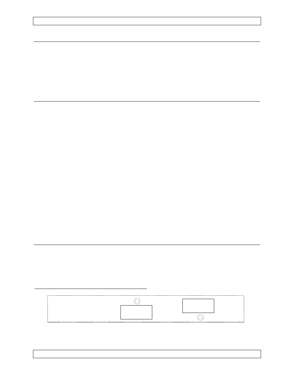
2.3.4.1
Right Side Panel Adjustments
MIC
LEVEL
ICS GAIN
LEVEL
The ICS GAIN LEVEL trimpot adjusts the internal gain of the intercom.
The MIC LEVEL trimpot is used to adjust the audio level of the pilot microphone.
Page 2-2
Dec 6, 2004
ENG-FORM: 805-0106.DOT
CONFIDENTIAL AND PROPRIETARY TO NORTHERN AIRBORNE TECHNOLOGY LTD.