1 qsdt8pcdp card, Video and audio pin layout, Connecting multiple cards – Q-See QSDT16PCRC User Manual
Page 7: Video capture card, Hardware and connections, Video capture card hardware and connections 12, Video capture card hardware and connections, Chapter 3
12
13
CHAPTER 3
VIDEO CAPTURE CARD HARDW
ARE AND CONNECTIONS
VIDEO CAPTURE CARD
HARDWARE AND CONNECTIONS
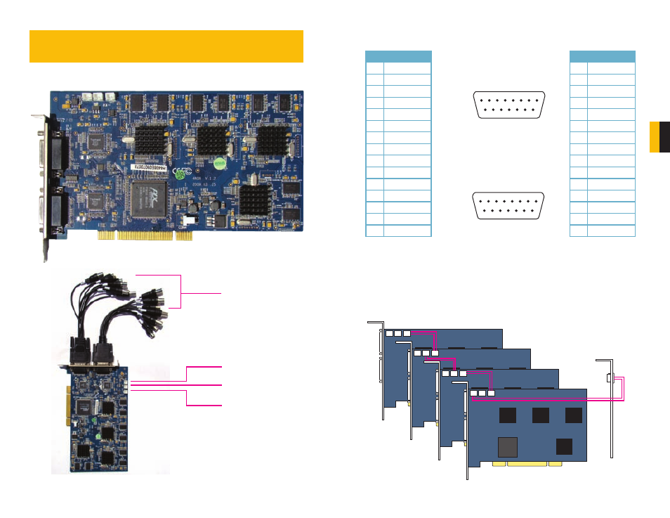
3.1 QSDT8PCDP CARD
PICTURE 3-2
PICTURE 3-3
PICTURE 3-1
Audio In and
Video In Ports
(4 Each)
CON 1 Port
CON 2 Port
Spot Out Port
VIDEO AND AUDIO PIN LAYOUT
P1
P2
CONNECTING MULTIPLE CARDS
You may control up to 32 cameras by installing up to four QSDT8PCDP cards. You will need
to connect the cards in the manner shown below to use the Spot Out option.
CHAPTER 3
P1
P2
Call
Monitor
Out
PICTURE 3-4
Video 1
GND
Video 2
GND
Video 3
GND
Video 4
GND
GND
Audio 1
Audio 2
Audio 3
Audio 4
Null
GND
PIN 1 2 3 4 5 6 7 8
PIN 9 10 11 12 13 14 15
Video 5
GND
Video 6
GND
Video 7
GND
Video 8
GND
GND
Audio 5
Audio 6
Audio 7
Audio 8
Null
GND
PIN 1 2 3 4 5 6 7 8
PIN 9 10 11 12 13 14 15
P2
P1
Video 1
GND
Video 2
GND
Video 3
GND
Video 4
GND
GND
Audio 1
Audio 2
Audio 3
Audio 4
Null
GND
PIN 1 2 3 4 5 6 7 8
PIN 9 10 11 12 13 14 15
Video 5
GND
Video 6
GND
Video 7
GND
Video 8
GND
GND
Audio 5
Audio 6
Audio 7
Audio 8
Null
GND
PIN 1 2 3 4 5 6 7 8
PIN 9 10 11 12 13 14 15
P2
P1
Pin Connection
1
VIDEO-1
2
GND
3
VIDEO-2
4
GND
5
VIDEO-3
6
GND
7
VIDEO-4
8
GND
9
GND
10
AUDIO-1
11
AUDIO-2
12
AUDIO-3
13
AUDIO-4
14
NULL
15
GND
Pin Connection
1
VIDEO-5
2
GND
3
VIDEO-6
4
GND
5
VIDEO-7
6
GND
7
VIDEO-8
8
GND
9
GND
10
AUDIO-5
11
AUDIO-6
12
AUDIO-7
13
AUDIO-8
14
NULL
15
GND