3 external power alarm – Nevion SL-3GHD128128 User Manual
Page 13
SL-3GHD128128
Rev. D
nevion.com | 13
4 partitions:
Partition 1
Input
Partition 1
Output
1
1
1
1
2
2
2
2
…
…
…
…
32
32
32
32
Partition 2
Input
Partition 2
Output
1
33
1
33
2
34
2
34
…
…
…
…
32
64
32
64
Partition 3
Input
Partition 3
Output
1
65
1
65
2
66
2
66
…
…
…
…
32
96
32
96
Partition 4
Input
Partition 4
Output
1
97
1
97
2
98
2
98
…
…
…
…
32
128
32
128
3.3 External power alarm
The external power alarm can be switched according to the following pattern:
SW 7
Power alarm
OFF
Disables External Power Alarm
ON
Enables External Power Alarm
Default setting is External Power Alarm disabled.
The Power Alarm GPI output will generate a contact closure if the internal
voltage is below a certain threshold, regardless of the position of DIP #7. This
DIP switch only determines if a faulty external power supply shall generate an
alarm/contact closure.
This means that enabling this power alarm should only be considered if you
have connected both external power supplies, for redundant supply. Then, a
contact closure will be generated if any of the connected power supplies fail.
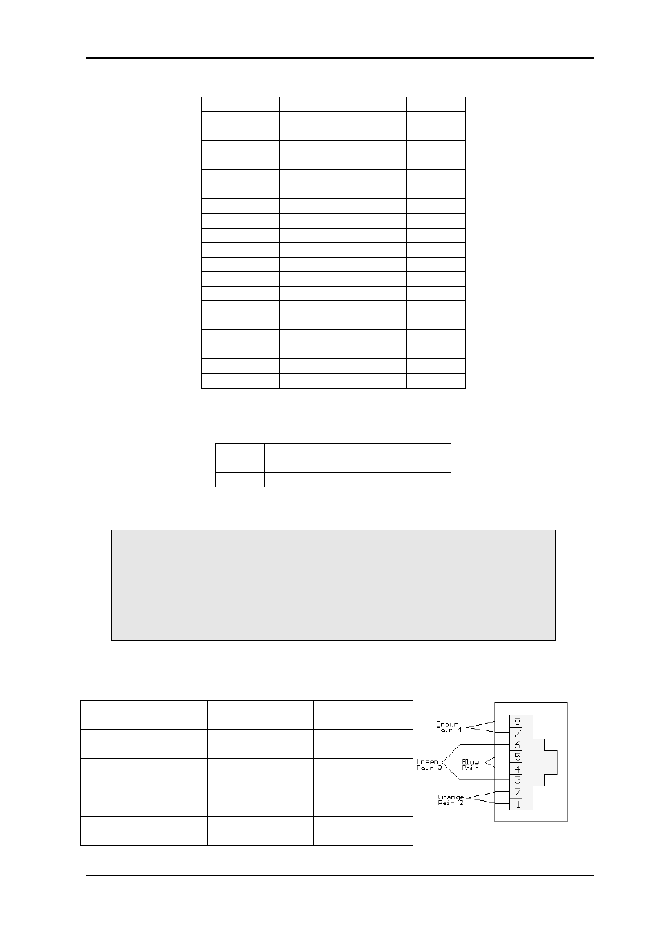
The associated power fail alarm relay contact, on the rear side of the frame, is described in
Chapter 2.5. The relay contact is normally open, and the contact closes according to the
description in this chapter.
Pin #
Signal
Name
Mode
1
Not in use
Input
2
Not in use
Input
3
Not in use
Input
4
Not in use
Input
5
PSU Alarm
Power alarm as
described above
Open Collector
6
Not in use
7
+5V
+5V pin
+5V
8
GND
0V / Ground
GND