5 operation, 1 module status - light emitting diodes, Summary: green leds are good, red leds are bad – Nevion ADC-SDI User Manual
Page 11: 1 card state, No light, Yellow, Green, Adc-sdi is powered and ready, 2 state of input channel 1, Channel 1 is inactive
ADC-SDI
Rev.
6
5 Operation
5.1 Module status - Light Emitting Diodes
Summary: Green LEDs are good, red LEDs are bad.
ADC-SDI implements four Light Emitting Diodes (LEDs) that show the state of the card. The
LEDs are visible through the front-panel of the rack (see the user manual of FR-2RU-10-2 for
details). The LEDs are described top-down, see also Figure 3.
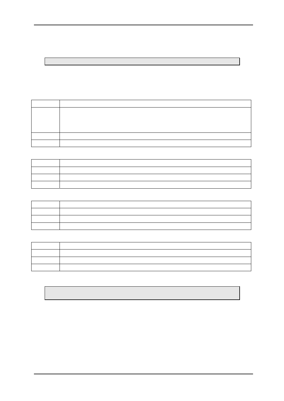
5.1.1 Card State
No Light
No power, fuse F1 blown, LED malfunction or configuration memory lost.
Red
A fundamental, probably electrical, error has been detected. The card is set in a
passive state, so that it does not disturb other cards in the rack. While powering
on, the CardState LED will light red for approximately 0.5 s while the card
undergoes self-test.
Yellow
The startup-sequence is running. The card is not yet ready
Green
ADC-SDI is powered and ready.
5.1.2 State of input channel 1
No Light
Channel 1 is inactive.
Red
ADC-SDI tries to detect input signal on channel 1.
Yellow
Input signal is detected on channel 1, but not yet locked.
Green
Input signal on channel 1 is detected, and properly locked.
5.1.3 State of input channel 2
No Light
Channel 2 is inactive.
Red
ADC-SDI tries to detect input signal on channel 2.
Yellow
Input signal is detected on channel 2, but not yet locked.
Green
Input signal on channel 2 is detected, and properly locked.
5.1.4 SDI output
No Light
Not used.
Red
No SDI output, or SDI output not correct.
Yellow Not
used.
Green
Correct SDI output.
5.2 Switches
Summary: Most users will probably want switches 1, 6 and 10 in on position and
the rest in off position. All users should place switch 10 in the on position.
The ADC-SDI card implements a Dual-Inline switch (DIP-switch) that provides 10 individual
On/Off switches. The purpose of the switches is to offer you an easy interface to some
features of the ADC-SDI card, without the need of a GYDA controller. Table 2 gives the
general layout of the switches. The switches are numbered from '1' at the top and
downwards to the bottom, see Figure 3. A switch is on when the tap is displaced in direction
of the back-plane.
The ADC-SDI card is shipped with all switches, except switch 1, 6 and 10, in the Off-position.
Switch number 10 should always be in the On-position. The switches are discussed in logical
rather than numerical order.
network-electronics.com
|
11