Museum Technology Source KD-1 Proximity Switch User Manual
Kd-1 dimensions, Connecting kd-1 to external device
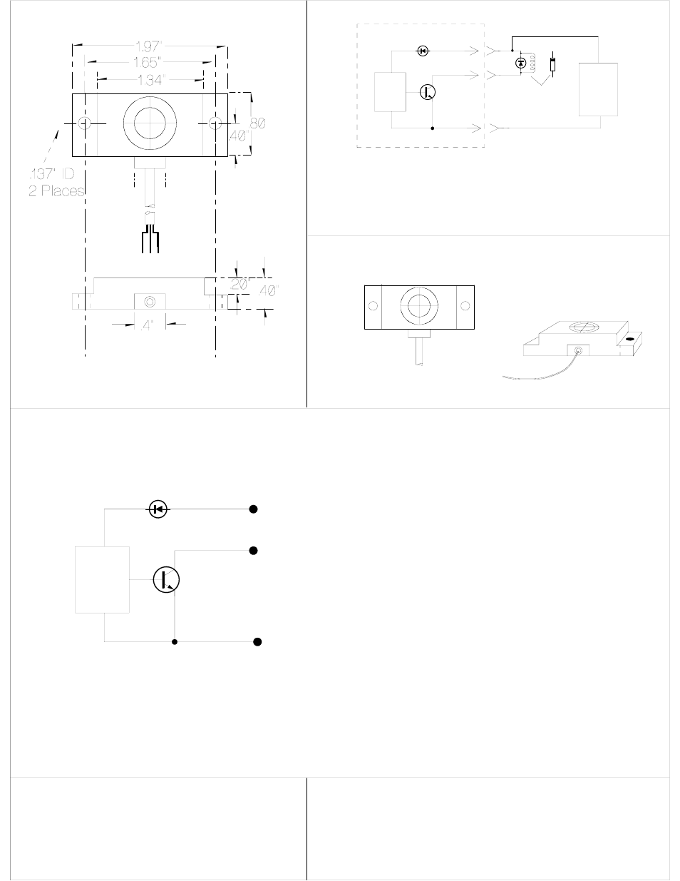
Control
Logic
Output
Transistor
NPN
Brown
Black
Blue
+V
Output
0 V
Supply Voltage: 12 to 30 VDC
@15 mA
Max Current: 100 mA
Max On State
Output Voltage: 1.5 V
Internal Reverse
Polarity Protection
Control
Logic
Output
Transistor
NPN
Brown
Black
Blue
+V
Output
0 V
Internal Reverse
Polarity Protection
Power Supply
10 to 30
VDC to
match
relay
+
-
Relay Coil
Diode such as 1N4004
must be placed as shown
across relay or solenoid
coil.
IMPORTANT
Cathode
Cathode
Anode
Anode
KD-1 Internal Circuit
External Circuit
Connecting KD-1 to External Device
KD-1 requires a supply voltage in the range of
12 to 30 volts DC. Current draw 15 mA (.015 Ampere)
The KD-1 will switch ON when a finger is held within
approximately 3/8 inch of the target. The KD-1 may
be mounted behind non-metallic material such as
Plex-glas or MDF. In general, this material should
be no thicker than 1/4 inch.
Connect to positive supply voltage
Connect to device to be activated
Conducts to common terminal when active
Connect to Negative of power supply.
Also connects of common of circuit being switched.
POSITIVE
NEGATIVE
KD-1 CAPACITANCE SWITCH
INSTALLATION SHEET
Museum Technology Source Inc.
Wilmington Massachusetts 01887
800-729-6873 978-657-3898
www.museumtech.com
March 2004
Limit current through output transistor
(Black lead) to 100 mA. Exceeding this
limit may result in damage to the KD-1
6' 6" Cord
.110" OD
KD-1 Dimensions
Revised April 4 2006