Drive roll and idler rolls – MK Products Cobra MX LE Com ACWC User Manual
Page 10
Cobra
®
MX Lincoln Compatible™ Owner's Manual - Page 3
adjustment screw, it closed the gap between the trigger lever and the micro
switch lever.
This will enable the operator to increase the sensitivity of the trigger lever.
Sensitivity Adjustment
With the wire feeder turned on (with or without welding wire loaded), turn the
screw in until the micro-switch is activated. Once activated, the torch and
wire feeder motors will begin feeding wire. Retract the screw accordingly until
the system is deactivated and adjusted to the operators' liking.
Drive Roll and Idler Rolls
General
The Cobra MX
Lincoln Compatible gun comes standard with a knurled drive
roll and a grooved idler roll, which will handle both hard wire and aluminum
wire with diameters of .030 to 1/16 inch and steel from .030 to .045 inches.
Optional insulated V-groove drive rolls are also available for aluminum wire if
desired (see optional kits).
Drive roll tension is accomplished with a unique spring-loaded pressure
screw. The Cobra MX
Lincoln Compatible comes from the factory with
the pressure adjustment screw preset.
NO ADJUSTMENT IS
rEQUIrED For ALL SIzES AnD TyPES oF WIrES
.
Drive Roll Installation/Removal
Note: Neither of the handles needs to be removed to access the drive or
idler rolls.
1. Pull the cam lever away from the idler roll.
This will relieve the pressure against the
drive roll (as shown in Figure 1).
2. Align the drive roll removal tool (P/N 931-
0100) over the flats of the drive roll (as
shown in Figure 2). Hold the gun with one
hand or on a table top, with the other hand
give the removal tool a quick snap-turn in
the CLOCKWISE DIRECTION.
3. Once the drive roll is loose, continue to
spin drive roll in the clockwise direction to
remove the drive roll from the gun.
4. Install a new drive roll on the left-hand threaded shaft. The drive roll will
self-tighten when it is feeding wire.
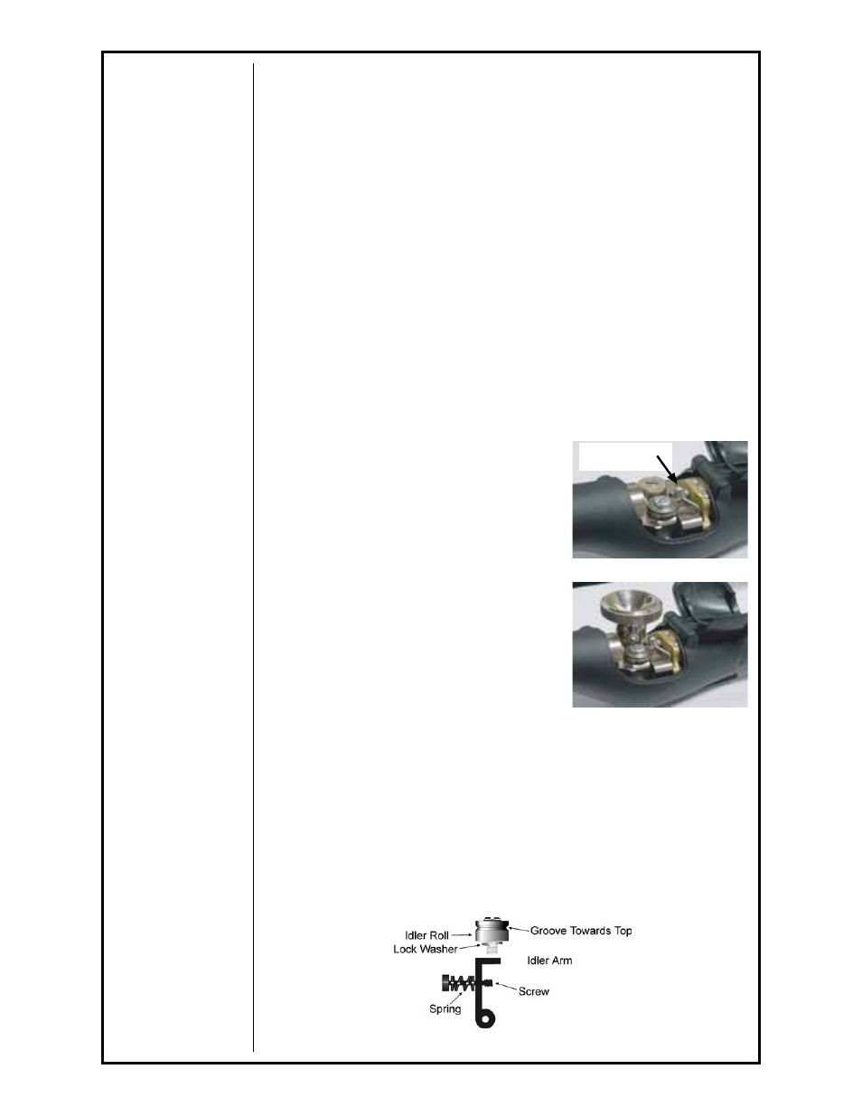
Idler Roll Installation and Removal
(Reference Figure 3)
1. Using a slot type screwdriver, loosen idler screw, taking care not to lose
lock washer under idler roll.
2. Insert new idler roll and lock washer onto screw, insuring that idler groove
is toward top and lock washer is beneath.
3. Tighten.
NOTE: Lock washer must be under idler roll or it will not turn freely.
Cam Lever
Figure 2
Figure 1
Figure 3