MK Products MK200 User Manual
Page 9
MK200 Owner’s Manual - Page 9
Section A
Installation
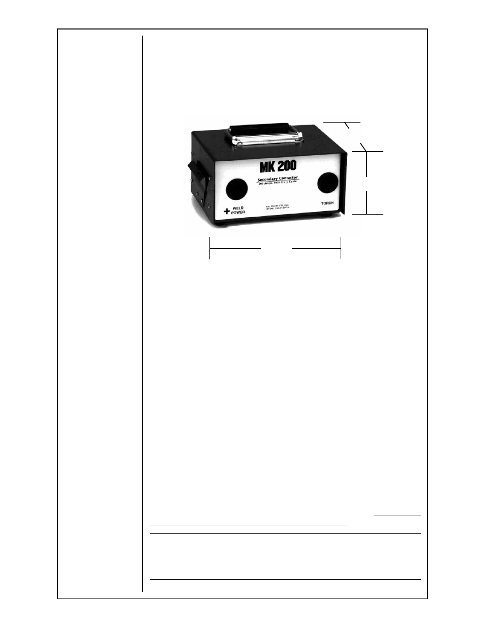
Specifications
Duty Cycle 60% at 250 amps
Weight 7 lbs. 4 oz.
Shipping Weight 9 lbs.
General
The Contactor Box is designed to be mechanically fastened to the top of
the WC-1 and includes a handle, making it easy to move the system to any
desired location. To mount the Contactor Box to the WC-1, remove the clips
from the side of the Contactor Box and insert the lips of the securing clips
into the louvers of the WC-1.
Power Leads
The positive lead from the welding power source is connected to the “+ weld
power” side and the Prince power lug is connected to the “Torch” side.
Control Leads
The cable from the Contactor Box connects to the 120 VAC contactor control
terminal inside the WC-1. Remove the lid from the WC-1 and insert the
cable from the Contactor Box through the strain relief. Connect the white
wire to
J5 terminal #3, the black wire to J5 terminal #4, and the green wire
to ground post.
See diagram on next page.
Section B
Operation
Hookup to Cobramatic
When using with the Cobramatic wire feeder system connect the 115VAC
contactor leads directly to the terminal strip inside the MK200, connecting
the white wire to
terminal #1 and the black wire to terminal #2, make sure to
switch the contacts to 115VAC output on the wire feeder.
NOTE:
When using the Contactor Box with equipment other than the WC-1, attach 115VAC
contactor NEUTRAL wire to Terminal 1 and the 115VAC contactor HOT wire to
Terminal 2 of the Contactor Box.
4 1/2"
9 3/4"
7 1/4"
Size 9 3/4"L x 4 1/2"H x 7 1/4"W