Optional kits – MK Products Cobra SX User Manual
Page 11
Cobra
®
SX Owner's Manual - Page 3
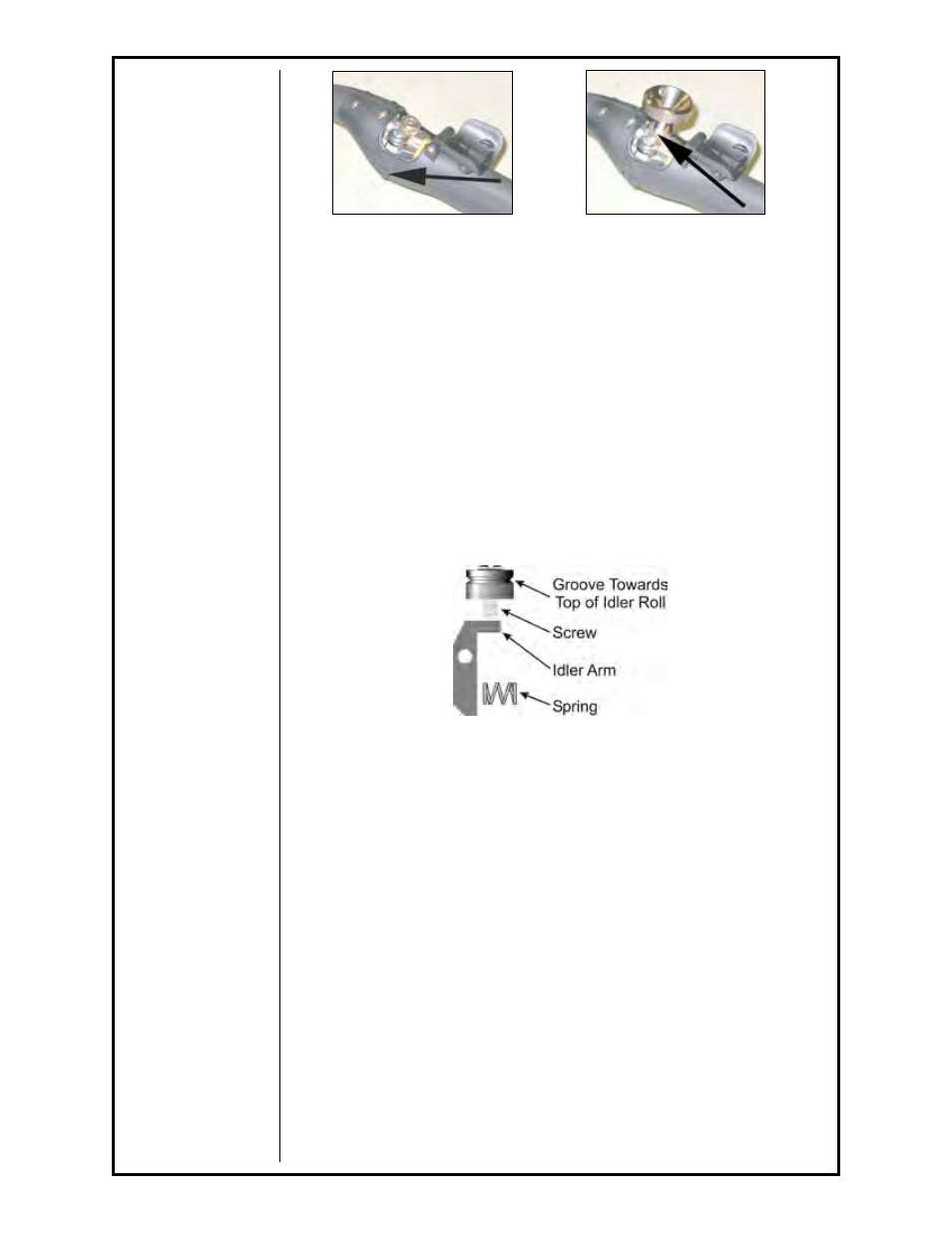
1. Push the idler lever, this will relieve the pressure against the drive roll (as
shown in Figure 3).
2. Align the Drive Roll Removal Tool (P/N 931-0100) over the flats of the
drive roll (as shown in Figure 4). Hold the gun with one hand or on a
table top, with the other hand give the Removal Tool a quick snap-turn in
the CLOCKWISE DIRECTION.
3. Once the drive roll is loose, continue to spin drive roll in the clockwise
direction to remove the drive roll from the gun.
4. Install a new drive roll on the left-hand threaded shaft. The drive roll will
self-tighten when it is feeding wire.
Idler Roll Installation and Removal
(Reference Figure 5)
1. Using a slot type screwdriver, loosen idler screw.
2. Insert new idler roll onto screw, insuring that idler groove is toward top.
3. Tighten.
Section C
Accessories
A gas flow control mechanism (i.e. solenoid or valve) is required so the
Cobra
®
SX
can be used on Cobra
®
SX wire feeders. The following kits
are available depending on the wire feeder used. The factory set times (in
seconds) for Normal and Latched Trigger functions is 0.25 pre-purge and 1.0
post-purge.
Optional Kits
The arcing of the wire at the knurled drive roll is typical of a contact tip which
is too large for the wire or if the aluminum wire has excessive oxidation,
reducing the contact between the wire and contact tip. Insulated Drive Roll
Kits are used when the teeth on the knurled drive roll, arc to and soften the
wire as it enters the barrel liner. The softened wire has a greater potential of
being shaved and/or clogging in the barrel liner.
Insulated Groove Drive Roll Kit
......................................................005-0640
For
.030" (0.8mm) dia. aluminum wire. Includes insulated drive roll
and idler roll assy.
Insulated Groove Drive Roll Kit
......................................................005-0716
For
.035" (0.9mm) dia. aluminum wire. Includes insulated drive roll
and idler roll assy.
Figure 3
Figure 4
Figure 5