Linear encoder installation, Chipencoder™ ce300 – MicroE CE300 ChipEncoder User Manual
Page 4
Attach the scale to the linear stage. Reference the preferred datum on the
interface drawing for either end or center index orientation.
Attach the scale to the slide with adhesive. Refer to page 6 for details
about the different methods available.
Be sure the grating surface of the scale faces the sensor. There is to be no
contact between the CE300 and the grating or damage may result.
2
The ChipEncoder CE300 should be installed on a printed circuit board (PCB) to
the electrical and mechanical specifications outlined on the interface drawings.
See page 5 for instructions on downloading interface drawings; and pages
3, 4 and 5 for information about the CE300, and CE300 to PCB assembly
instructions.
3
Page 4
If you wish to verify the encoder outputs using a digital oscilloscope to view
the A, B, and Index Window signals, please refer to page 4 for output signal
descriptions. The CE300 should not require any additional alignment as long
as the PCB and mechanical components have been fabricated and assembled
according to the mechanical dimensions and tolerances specified in the CE300
interface drawings.
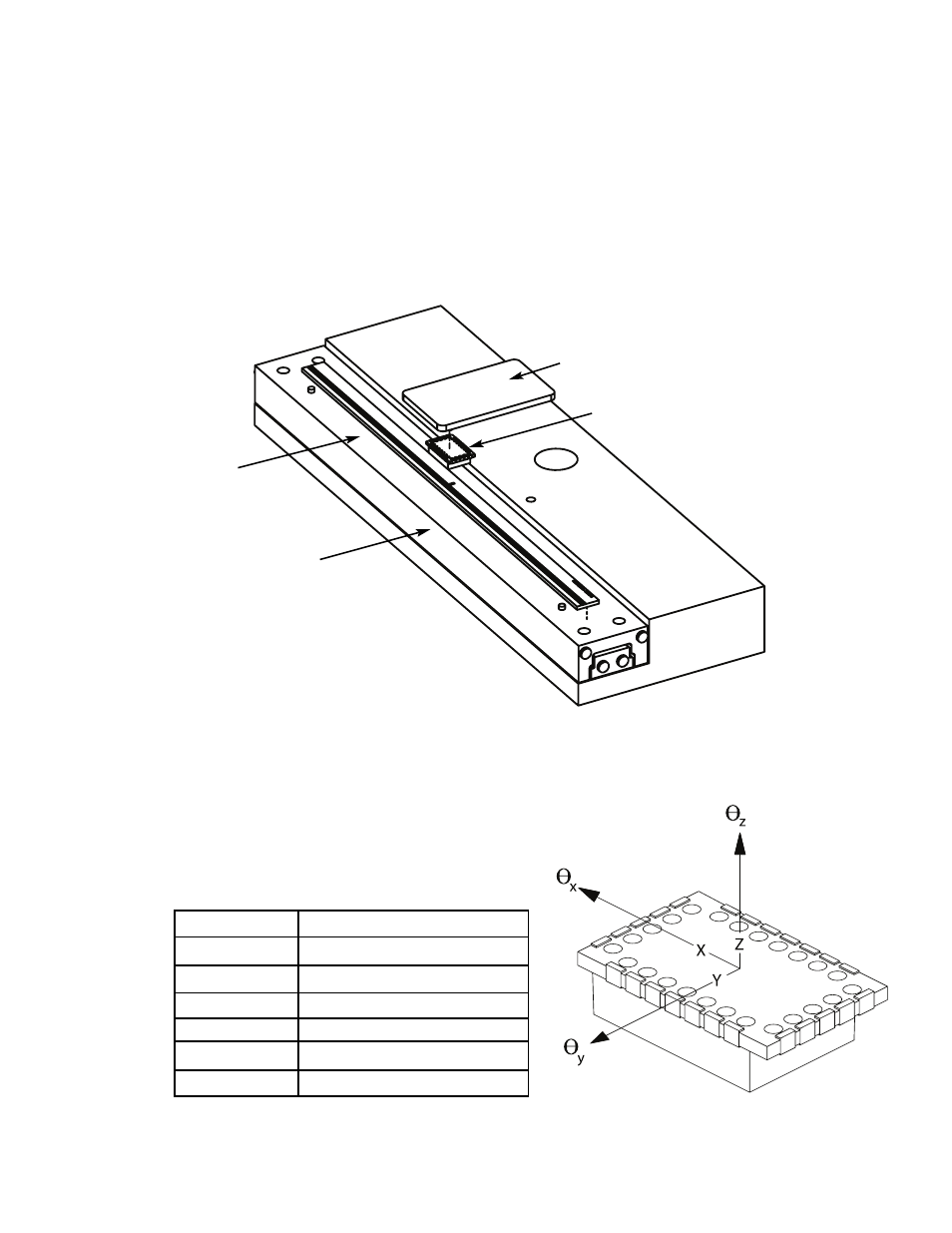
ChipEncoder™ CE300
Encoder Mounting with Linear Scale
PCB
ChipEncoder
Linear Scale
Linear Stage
Axis
Alignment Tolerances
x
direction of motion
y
± 0.008” [0.20mm]
z
± 0.010” [0.25mm]
θ
x
± 1.5°
θ
y
± 1.5°
θ
z
± 2.0°
1