Methven Tahi Thermostatic Mixer Valve (2 Outlets) User Manual
Page 2
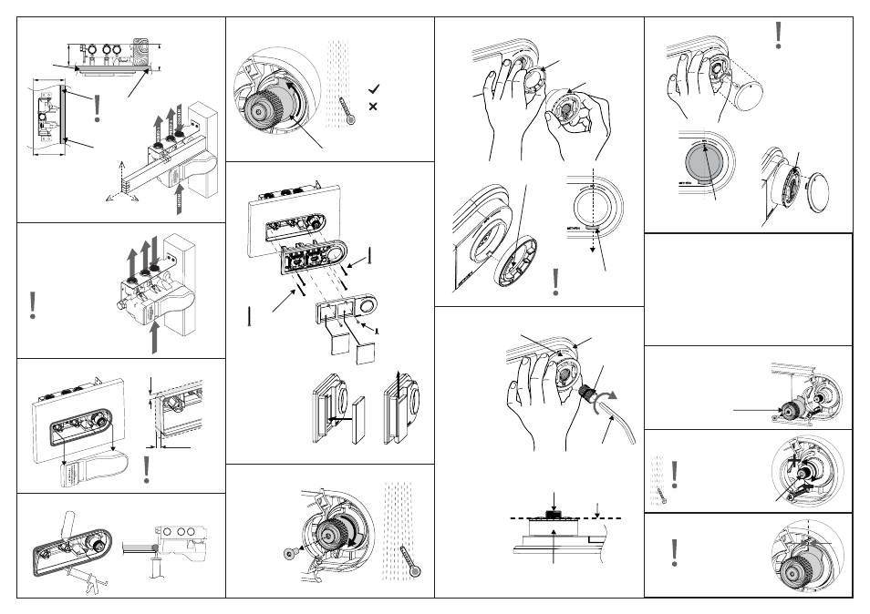
Remove screw.
Do not discard.
Rotate temperature
A.
stop fully anti-
clockwise
If temp ≤ 46°C
B.
If temp > 46°C
Adjust (see
commissioning)
COMMISSIONING -
The Tahi thermostatic mixer valve is factory set to the required temperature.
Check the valve after installation to ensure it operates at the correct outlet
temperature.
Prior to commissioning the Tahi thermostatic mixing valve check the following:
The designation of the thermostatic mixing valve matches the application.
●
The supply pressures are within the valves operating range.
●
The supply temperatures are within the valves operating range.
●
Isolating valves (and strainers preferred) are installed.
●
REMOVE MAXIMUM TEMPERATURE STOP
Remove screw.
A.
Do not discard.
Rotate clockwise
B.
until water temp
= 38°C
NOTE - Use of supply
line or zone strainers is
strongly recomended.
1
MOUNT
PARALLEL TO
WALL LINING
2
P < 1000 kPa/10 bar
(Test pressure must not
exceed 1000 kPa/10 bar)
CHECK WATERTIGHTNESS
3
FIT WALL LINING AND REMOVE DUST COVER
USE PROVIDED
TEMPLATE FOR
ACCURATE HOLE
DIMENSIONS.
6mm MAX
6mm MAX
4
Wall lining
Tiles
TRIM FLUSH AND SEAL WITH SILICON
5
CHECK MAX OUTLET TEMPERATURE
6
FIT TRIM COMPONENTS
7
SET WATER TEMP TO 38°C
8
ASSEMBLE DIAL GUIDE AND DIAL
Dial
guide
Dial
DOWNWARD ORIENTIATION
OF BUTTON CRITICAL
9
ASSEMBLE HEIGHT ADJUSTOR
Hold dial
A.
hard against
faceplate.
Wind depth
B.
adjustor into
dial. Stop when
you feel dial
starting to push
away from the
faceplate
Faceplate
Depth adjustor
8mm Allen key
Dial
If depth adjustor
C.
protrudes past
the front face of
the dial; Remove
the depth
adjustor and
trim at midpoint
(cut in half).
Reassemble as
per steps 9: A
and B
10
Insert and tighten
A.
screw using
2.5mm Allen
key (finger tight
only) to fix dial
position.
Fit cap (force
B.
required)
Tip: Insert dot end
of cap first
HOLD DIAL TO STOP
ROTATION WHILST
TIGHTENING.
FIT DIAL CAP
Note: Dot orientation on dial
cap is at top (opposite dial
button).
1
2
TEMPERATURE
MUST NOT
EXCEED 46°C
ADJUST TEMPERATURE TO
DESIRED MAXIMUM.
3
REASSEMBLE MAXIMUM
TEMPERATURE STOP
Assemble with faces
aligned as shown
Note: Do not Rotate
cartridge control knob
while assembling
Maximum temperature
stop
Maximum temperature stop
x 2 (long screws)
x 2 (short screws)
x 2 (Allen screws)
VER
TICAL
=
=
96-116mm
OPTIMUM = 106mm
=
=
PARALLEL
MOUNT MIXER BODY IN WALL CAVITY
NOTE - Levers to be
inserted from bottom
as shown in diagrams
A and B
NOTE - Locating
feature
Trim
Depth Adjustor
Dial
Maximum temperature stop
Cartridge control knob
Wall lining
Wall lining
A.
B.