Methven Kiri User Manual
Page 4
4
5
It is Important to note at this stage, very hot water MAY flow through either outlet depending on
where the diverter is set too and can cause serious burns if care is not taken !!!.
3. Take note of the outlet temperature of the shower using a suitable testing equipment.
4. If the maximum temperature requires adjusting . Remove the Temperature control knob (3) and adjust
the Thermostatic mixing valve spindle.
To increase the outlet temperature , Slowly turn the spindle of the anti-clockwise
To decrease the outlet temperature , Slowly turn the spindle of the clockwise
5. When the desired temperature is achieved. Refit and secure the Thermostatic mixing valve control
knob (3) lining up the pin in the Knob with the Temperature stop ring(12).
6. Turn off the Shower valve.
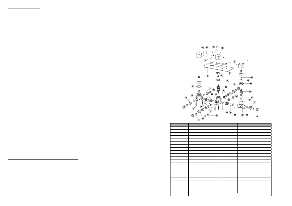
Parts Reference Drawing
Installing the Product
When installing the assembly into the wall cavity , for ease of installation and maintenance you should aim to
keep the access hole as large as possible whilst ensuring there will still be enough room to be able to create
a suitable contact between the wall and concealing plate using a suitable silicon sealant to create a water tight
joint between the wall and concealing plate.
This product has been designed to fit in a cavity with a minimum depth of 60mm. For deeper cavities you may
need to create a suitable mounting bracket in the cavity to securely mount the valve assembly. We recommend
a mounting depth of between 60/67mm from the front face of the tiles. Failure to take this into account will mean
that the concealing plate will not be able to be fixed onto the valve assembly. Refer to Page 7 ‘Line drawing’.
1. Ensure that both the Hot and Cold mains water supplies are isolated.
2. Fix the shower valve assembly into the wall cavity ensuring the diverter assembly is at the top and the bath
fill on / off control is at the bottom. If done correctly the ‘Hot’ inlet port to the thermostatic mixing valve will be
in the centre of the valve assembly to the left hand side.
3. Connect the respective Hot and Cold water supplies to the Hot and Cold inlet ports of the thermostatic
mixing valve making sure that all seals, filters olives are fitted and joints sufficiently tightened.
4. Connect the left hand diverter outlet to one of your outlets and the right hand diverter outlet to the
other outlet connection and the bath fill outlet to the bath fill.
Important : Before fitting the concealing plate it is essential that all joints are checked for leaks. Failure to do
so could result in flooding or water damage within the cavity over a long period of time that may
not be immediately evident. Therefore :-
5. Secure the Diverter knob (2) to the Diverter assembly (31) and Bath fill on/off knob (2) to the stopcock
assembly.
6. Secure the temperature control knob to the thermostatic mixing valve (32). To secure the temperature
knob in the correct position . Please refer to ‘Maximum temperature setting and adjustment’.
7. Ensuring all joints have been secured and tightened , Turn on both Hot and Cold water supplies.
8. Turn the diverter knob towards the side connected to bath fill outlet.
9. Taking care , turn on the thermostatic mixing valve. If no water appears from the outlet of the bath fill ,
rotate the bath fill on/off knob. Water should now be flowing through the bath fill outlet, check all joints
for signs of leaks . Turn off the bath fill on/off knob. Turn the diverter knob towards one of the other
connected outlets. Water will now flow through this outlet. Repeat this process for the remaining outlet.
Any leaking joints should be immediately rectified. It may be a good idea to leave the shower running for
several minutes to ensure the joints are water tight and no leaks appear.
10. When you are confident that all joints are watertight. Turn off the thermostatic mixing valve.
11. Noting each of the three control knob positions , remove the bath fill , thermostatic mixing valve and
diverter control knobs (The positions will be required after fitting the concealing plate to refit the control
knobs in the correct operating positions).
12. Ensuring correct orientation, Fit the concealing plate (28) to the valve assembly. When fitting the
concealing plate , a suitable sealant should be used to create a waterproof joint between the concealing
plate and wall.
13. Refit and secure the Diverter control knob to the position it was removed in point 11.above.
14. To refit the thermostatic mixing valve temperature knob , Please refer to ‘Maximum temperature
setting and adjustment’.
15. Refit and secure the bath fill control knob to the position it was removed in point 11.above.
Maximum Temperature Setting and Adjustment
Whilst the Temperature of your Thermostatic mixing valve has been factory tested and calibrated, you will
need to perform a slight initial adjustment to suit your system operating setup. To do so :-
1. Loosely fit the Thermostatic mixing valve control knob (3) to the Thermostatic mixing valve. Note, whilst
fitting the Knob, there is a Temperature stop pin (17) inside the knob which is required to line up with the
Temperature stop ring (12).
2. Taking extreme care, Slowly turn on the Thermostatic mixing valve and gently rotate the control knob
to the maximum temperature position. Let the shower run for several minutes to ensure the correct
blend of Hot and Cold water and the maximum outlet hot water temperature has been achieved.
Part
Code
Description
Part
Code
Description
1
00105055
Valve Body
24
00512119
Connector
2
00142875
Diverter Handle
25
00514592
Connector
3
00142872
Temperature Handle
26
00515537
Shroud
4
00400014
O' Ring
27
00515826
Adaptor
5
00400015
O' Ring
28
00550740
Plate
6
00400246
Filter Washer
29
00601113
Pair of Fixing Screws and Plugs
7
00400380
O' Ring
30
00603719
Check Valve
8
00400648
O' Ring
31
00604189
Diverter Assembly
9
00411240
Spline Adaptor
32
00650492
Thermostatic Cartridge
10
00410544
Handle Cap
33
00940006
Seating Ring
11
00411048
Temperature Over ride Button
34
00400262
O' Ring
12
00411057
Temperature Stop Ring
35
00400008
O' Ring
13
00411171
Plastic Spacer
36
00500219
Grub Screw
14
00411398
Flow Regulator 10 l/min LP
37
00141699
Stopcock Body
15
00500144
Grub Screw
38
00400030
O' Ring
16
00500222
Spring
39
00512115
Connector
17
00500492
Temperature Stop Pin
40
00400100
O' Ring
18
00500700
Grub Screw
41
00512619
Stopcock valve seat
19
00510133
Nut
42
00650307
Stopcock Valve
20
00511135
Nut
43
00515922
Adaptor
21
00511137
Olive
44
00501037
Spacer
22
00511258
Connector
45
00500746
Stopcock Spline Extended Screw
23
00512620
Connector