Mathey Dearman 1SA Saddle Machine User Manual
Page 8
8
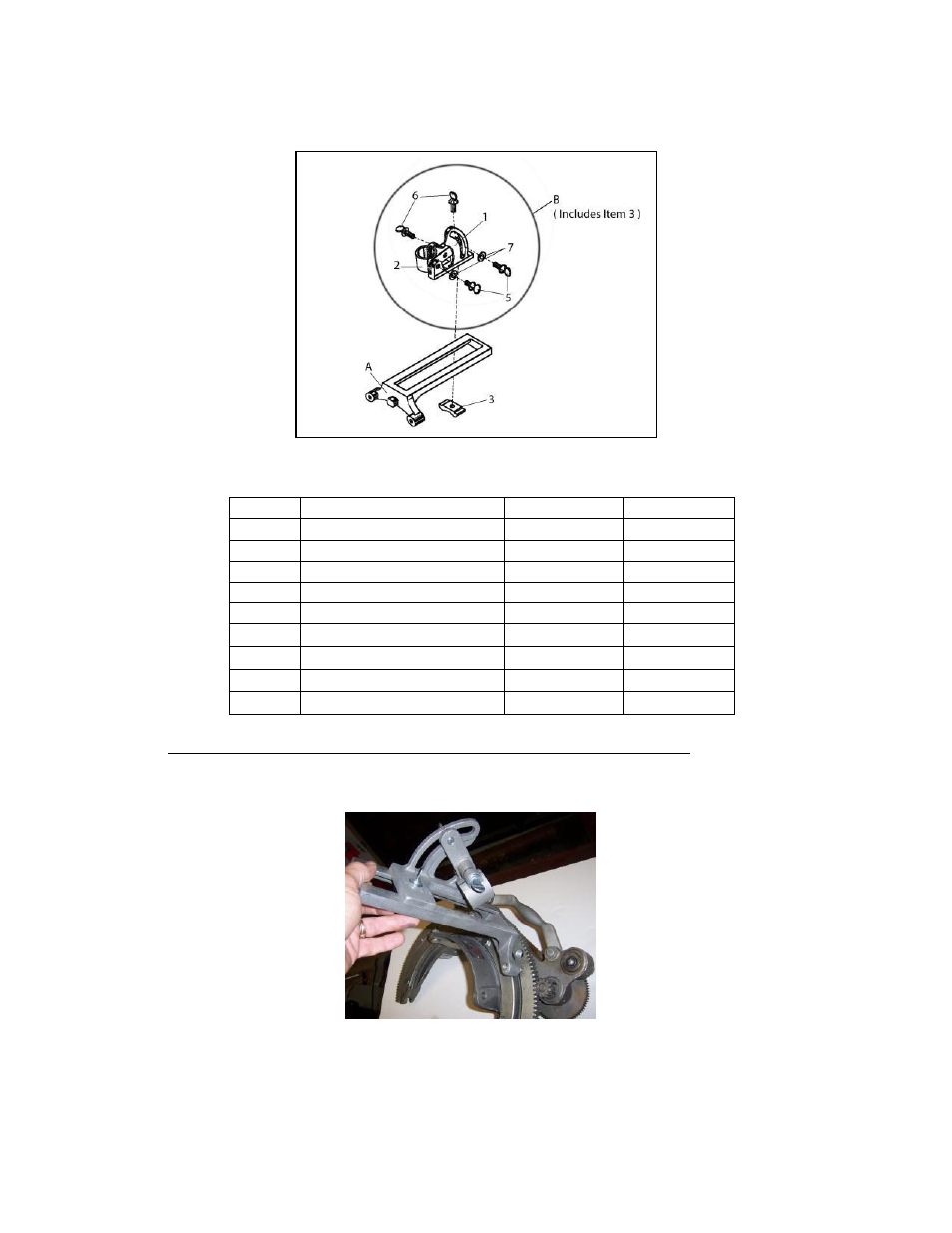
Figure 4: Torch Arm
Part Number: 03-0101-001
Torch Carrier Assembly
Part Number: 03-0100-002
Table 4 – Boomer Assembly Parts Identification
ITEM #
PART DESCRIPTION
PART #
QUANTITY
A
Torch Arm
03-0101-001
1
B
Torch Carrier Assembly
03-0100-002
1
1 Torch Clamp Base
03-0100-003
1
2 Torch Clamp
03-0100-005
1
3 Clamp
03-0100-004
1
4 Screw Kit (includes 5, 6 & 7)
03-0100-029
1
5 Thumb Screw, 3/8-16 x 3/4”
22-38TS-034
2
6 Thumb Screw, 3/8-16 x 1”
22-38TS-100
2
7 Flat Washer, 3/8”
12-0038-F00
2
6.0
Installation of Torch Arm, Torch Carrier Assembly and Torch
6.1
Install Torch Arm (Figure 4, Item A) over the two threaded studs (Figure 5 item 14) in the face of the 1SA
Machine Ring Gear (Figure 5 Item 3).
Picture 5 – Installation of Torch Arm on Threaded Stud
6.2
Secure the Torch Arm (Figure 4 item A) to the Ring Gear (Figure 5 item 3) with the wing nuts (Figure 5 item 15)
provided in the Spacer Bolt Box.