Fig. 1, Installation and operating instructions – Louroe Electronics DA-4 User Manual
Page 2
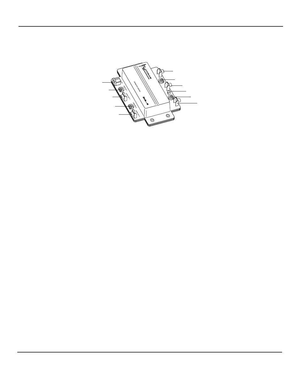
AUDIO INPUT
GAIN ADJUST FOR AUDIO OUT #4
AUDIO OUTPUT #4
POWER LED
GAIN ADJUST FOR AUDIO OUT #3
AUDIO OUTPUT #3
12 VDC POWER JACK
GAIN ADJUST FOR AUDIO OUT #1
AUDIO OUTPUT #1
GAIN ADJUST FOR AUDIO OUT #2
AUDIO OUTPUT #2
Description of Functions
Fig. 1
Connecting a Louroe microphone directly to the DA-4
(Refer to figure 3, page 5 of this instruction)
All Louroe microphones contain a 3-pin terminal block marked A, B, C
A = +12Vdc power
red wire
B = Audio Output
black wire
C = Ground
bare wire
Microphone’s current drain is 10mA.
IApplying Power to the Microphone
Apply 12Vdc power to terminals A and C. A is positive and C is negative
Microphone Connection to DA-4
a. Referring to the microphone 3-pin terminal block, connect a 22 gauge shielded cable to terminal B
and a ground wire to terminal C. (Terminal C is common for both 12Vdc power and audio output).
b. Run other end of cable to DA-4 and solder to an RCA plug. Wire from terminal B of microphone
goes to the tip of the RCA plug and ground wire goes to the sleeve.
c. Connect RCA plug to “Audio Input” RCA jack of DA-4
INSTALLATION AND OPERATING INSTRUCTIONS
Page 2 of 4
LOUROE ELECTRONICS 6 9 5 5 VA L J E A N AVENUE, VAN NUYS, CA 91406
TEL (818) 994-6498
FAX
994-6458
website: www.louroe.com e-mail: [email protected]
(818)
®
DA_4_inst_3/15