Interconnection diagram, Installation and operating instructions, Wiring requirements – Louroe Electronics APR-1 User Manual
Page 5: Rear panel of apr-1 (dual rca included), Included)
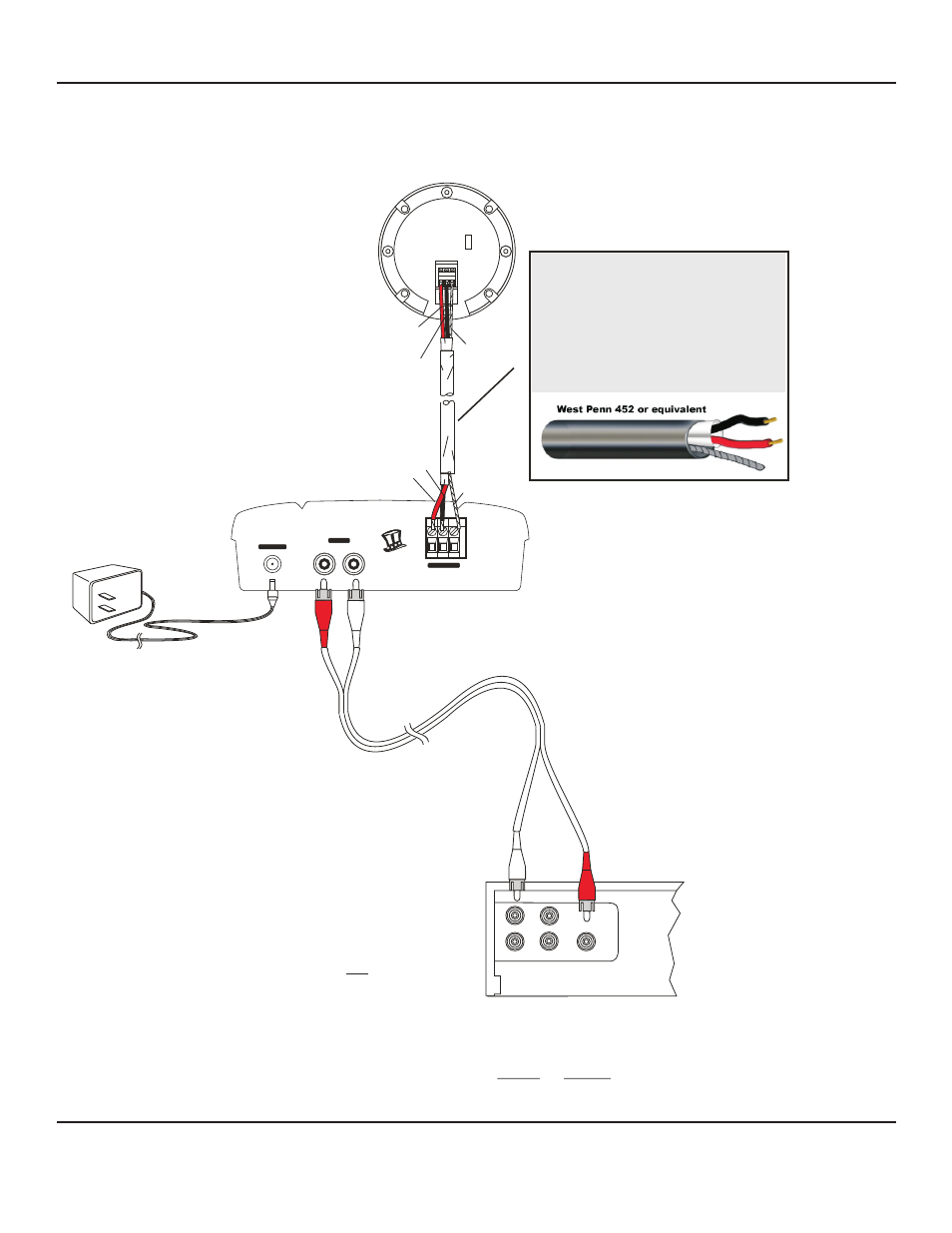
INTERCONNECTION DIAGRAM
AUDIO OUT
AUDIO OUT
AUDIO IN
AUDIO IN
N
I
E
U
D
S
A
A
M
+12 Vdc
INPUT
OUTPUT
AUDIO
B
A
C
MIC INPUT
VAN NUYS, CA
VERIFACT A MICROPHONE TO APR-1 BASE STATION TO DVR, VCR, ETC.
Rear Panel of APR-1 (Dual RCA included)
REAR PANEL OF DVR WITH
RCA TYPE AUDIO INPUTS
AD-1 AC Adapter
“Audio In” of APR-1
connects to “Audio Out”
of DVR or other receiving device
(Red RCA plug)
All Louroe Microphones
are compatible with the APR-1.
Verifact A Microphone
used as an example
NOTE: If DVR’s audio input and output are 3.5mm (mini jack) type, use the appropriate adapter
at one end of RCA patch cable for connection. Check with manufacturer’s specifications
to determine if 3.5mm audio input/output is mono or stereo.
“Audio Out” of APR-1
connects to “Audio In”
of DVR or other receiving device
(White RCA plug)
(A) Red - 12Vdc power
(B) Black - Audio Output
(C) Bare - Ground
2 Conductor shielded cable, 22
gauge with a 24 gauge drain
wire.
NOTE: Unshielded cable is not
satisfactory for audio
systems.
WIRING REQUIREMENTS
BARE
BARE
RED
RED
BARE
BARE
A B C
A B C
BACKSIDE OF
MICROPHONE
BACKSIDE OF
VERIFACT A
MICROPHONE
L
L
N
N
BLACK
BLACK
RED
RED
BLACK
BLACK
INSTALLATION AND OPERATING INSTRUCTIONS
(Included)
Page 5 of 8
LOUROE ELECTRONICS 6 9 5 5 VA L J E A N AVENUE, VAN NUYS, CA 91406
TEL (818) 994-6498
FAX
994-6458
website: www.louroe.com e-mail: [email protected]
(818)
®
APR-1_inst_2/15
®
®
®