Interconnection diagram, Installation and operating instructions, Wiring requirements – Louroe Electronics AOP-SP-CF User Manual
Page 3
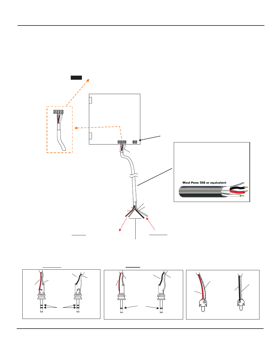
4-PIN TERMINAL BLOCK IDENTIFIER OF AOP-SP-CF/CS (A,B,C,SP)
A = not used with this application
(
) B = Audio Output
(
) C = Ground (audio) and Ground (speaker) (black wire)
(
) SP = Speaker output
red
bare
white
INTERCONNECTION DIAGRAM
CONNECTING LOUROE MODEL AOP-SP-CF/CS
DIRECTLY TO AN IP CAMERA, DVR,
VIDEO SERVER, ETC. USING 3-COND. SHIELDED CABLE
EXT
MIC
SPKR
+12Vdc
AUDIO
OUT
AUDIO
IN
TALKBACK
ADJUST
MIC
ADJUST
C
A
SP
B
LOUROE MODEL AOP-SP-CF/CS
PC BOARD
WHITE (SP)
BLACK (C)
(C) BARE
(B) RED
TO AUDIO OUT OF IP CAMERA, DVR, ETC.
TO AUDIO IN OF IP CAMERA, DVR, ETC.
NOTE: BLACK AND BARE WIRES ARE COMMON GROUND
BARE (C)
BLACK (C)
RED (B)
West Penn 358
or equivalent
C
A
SP
B
WHITE (SP)
Audio Out
Audio Out
Audio In
Audio In
Bare Wire
Red Wire
RCA CONNECTION
3.5mm MONO CONNECTION
3.5mm STEREO CONNECTION
White Wire
Black Wire
Black Wire
White Wire
Red Wire
Bare Wire
M
O
N
O
S
T
E
R
E
O
Audio Out
Audio In
Red Wire
Black Wire
White Wire
Bare Wire
WIRING REQUIREMENTS
3 Conductor consisting of:
+
2 Conductor shielded, 20 gauge
with 22 gauge drain
+
1 Conductor unshielded, 20 gauge
All in the same jacket
+12Vdc,500mA power required
(AD-1 power supply included)
AUDIO
OUT
AUDIO
IN
12 Vdc power is required to connect the AOP-SP-CF/CS
directly to an IP camera or DVR such as AD-1 power supply.
Positive 12Vdc connects to terminal marked “+”
Negative 12 Vdc or ground
connects to terminal marked “GND”
(wire with white stripe)
+12Vdc
+
GND
Page 4 of 8
INSTALLATION AND OPERATING INSTRUCTIONS
LOUROE ELECTRONICS 6 9 5 5 VA L J E A N AVENUE, VAN NUYS, CA 91406
TEL (818) 994-6498
FAX
994-6458
website: www.louroe.com e-mail: [email protected]
(818)
®
aopsp_cf/cs_inst 3/15