Louroe Electronics ASK-4 302 User Manual
Page 2
WIRING REQUIREMENTS
2 conductor shielded, 22 gauge, with a 24 gauge drain wire.
West Penn 452 or equivalent
MICROPHONE INSTALLATION - MECHANICAL
Model A Microphone is designed for surface mounting to a ceiling or wall. Microphone will pick up
sounds 15’ away from all directions. For best results, install microphone as close to desired area of
coverage as possible. Avoid mounting microphone to ceiling heights in excess of 10’, or near air
vents, refrigeration units, or other audio interferences.
NOTE: Make wiring connection on back side of microphone before installing microphone to ceiling or
flat surface.
MICROPHONE INSTALLATION - ELECTRICAL
Located on back side of microphone is a terminal block marked A, B and C.
A is 12 Vdc
B is Audio
C is Ground (common)
Using recommended wiring, connect as follows:
RED wire to terminal A
(12Vdc)
BLACK wire to terminal B (Audio)
BARE wire to terminal C
(Ground)
NOTE: If using wiring from other manufacturers,
color code may vary.
Repeat connections for the second microphone.
LOUROE MODEL IF-2 AUDIO INTERFACE ADAPTER
INSTALLATION AND OPERATING INSTRUCTIONS
Page 2 of 8
LOUROE ELECTRONICS 6 9 5 5 VA L J E A N AVENUE, VAN NUYS, CA 91406
TEL (818) 994-6498
FAX
994-6458
website: www.louroe.com e-mail: [email protected]
(818)
®
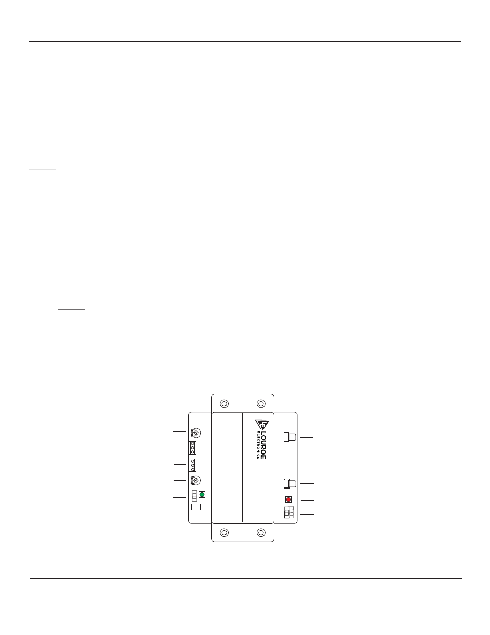
IF-2
2 Z
O
N
E
A
U
D
IO I
N
T
E
R
F
A
C
E
A
D
A
P
T
E
R
+12 Vdc
LEVEL CONTROL 1
LEVEL CONTROL 2
AUDIO INPUT
1
AUDIO OUTPUT
1
AUDIO OUTPUT
2
AUDIO INPUT
2
®
AUDIO OUT CONTROL 1
AUDIO OUT 1
AUDIO OUT 2
AUDIO INDICATOR
AUDIO TEST SWITCH
AUDIO OUT CONTROL 2
POWER SWITCH
POWER LED
POWER JACK
MICROPHONE INPUT 1
MICROPHONE INPUT 2
Ask4_302_inst_2/15