Caution – Dometic 630515.336 User Manual
Page 10
620515, 620525, 620526, 630515 & 630516 Installation Instructions
10
CAUTION
If bolts are left loose there may not be ad-
equate roof seal or if over tightened, damage
may occur to the air conditioner base or ceil-
ing template. Tighten to specifications listed
in this manual.
e.
Install the Romex connector in the junction box.
f.
Hold the ceiling template up to the 14-1/4" x
14-1/4" (±1/8") opening. Be sure the large plate
faces the rear of the RV.
g.
Start each mounting bolt through the ceiling tem-
plate and up into the unit base pan by hand.
Install wood screw in each end of the ceiling
template. This insures a tight fit of the return air
cover to ceiling. See FIG. 14. Evenly tighten
mounting bolts to compress gasket to 1/2"
this will be a torque of 40 - 50 inch pounds.
The bolts are self locking so over tighten-
ing is not necessary. See FIG. 15.
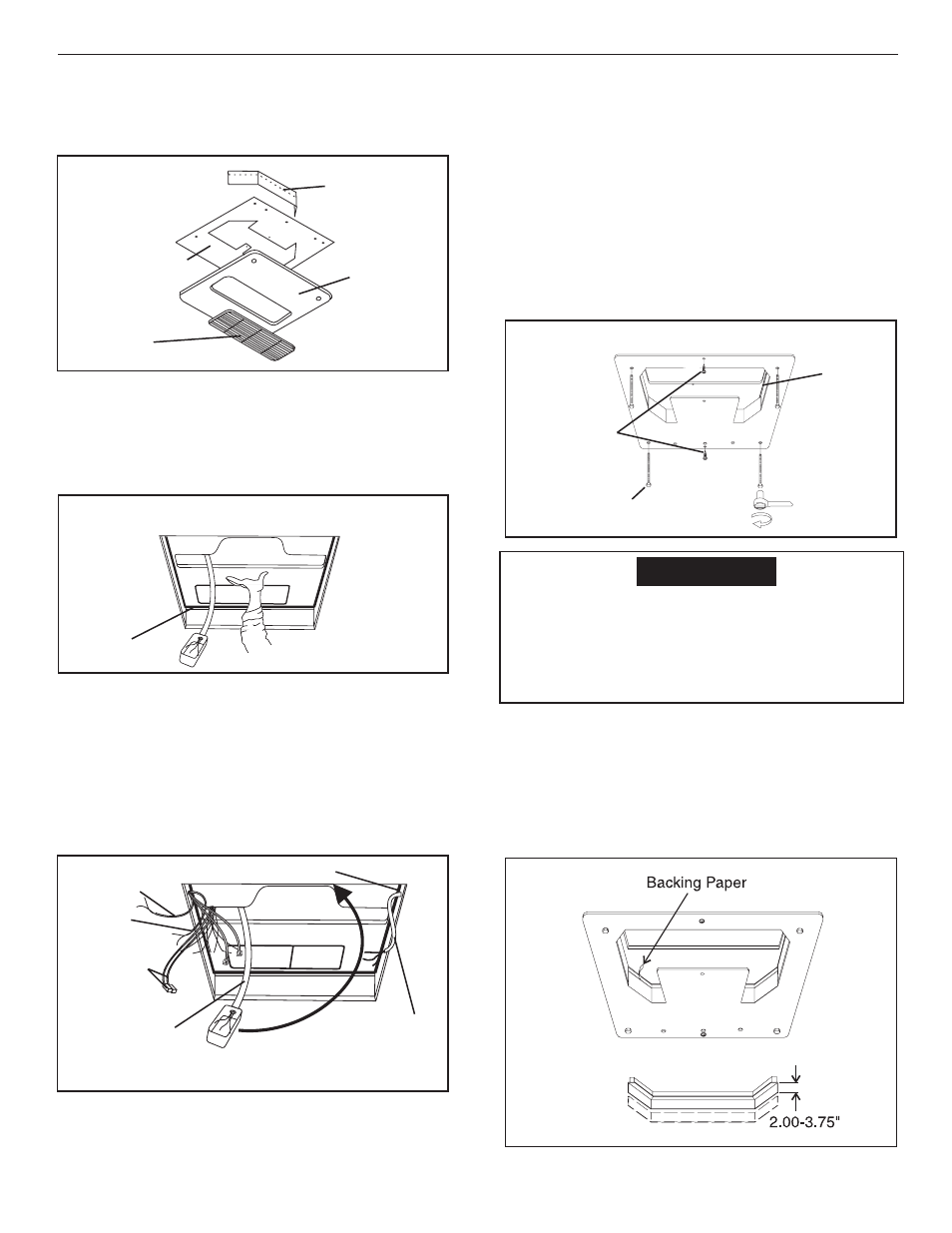
2.
Installation of Divider Plate
a.
Measure the ceiling to roof thickness:
•
If distance is 2.0" - 3-3/4", remove perfo-
rated tab from divider plate.
•
If distance is 3-3/4” - 5-1/2”, remove no tabs.
b. Remove the backing paper from double sided
tape located on ceiling template. See FIG. 16.
G. Installing The Air Conditioner
Installing Unit with 3105007 or 3105935 Return Air
Kit. For unit with Genesis Air Filtration System, see
page 11.
1.
Installation Of Ceiling Template
a.
Check gasket alignment of the air conditioner
over the roof opening and adjust if necessary.
Unit may be moved from below by slightly lift-
ing and moving. See FIG. 13.
b.
Remove return air cover and ceiling template
from the 3105007 or 3105935 carton.
c.
Locate the four (8" x 1/4- 20) unit mounting bolts,
junction box cover and Romex connector in the
3107180 bolt kit.
d.
Pull down the unit's electrical cord and fasten
the junction box with screws to the framing in
the front of the 14-1/4" x 14-1/4" (±1/8") open-
ing. See FIG. 14.
FIG. 12
Divider Plate
Ceiling Template
Return Air
Cover
Return Air
Grill
FIG. 13
Center Unit From Below
Roof
Gasket
DC Power
Gasket
Pull Electrical
Cord Down
FIG. 14
AC Power
Supply
Fasten Jct. Box To
Front Of Opening
Furnace
Unit CCC
Connectors
FIG. 16
FIG. 15
Finger
Tight
Front of Vehicle
Tighten to
compress gasket
to 1/2"
Roof
Gasket
Screws