Installation, H* c – Lacava 7000 User Manual
Page 3
LACAVA LLC
3
Installation
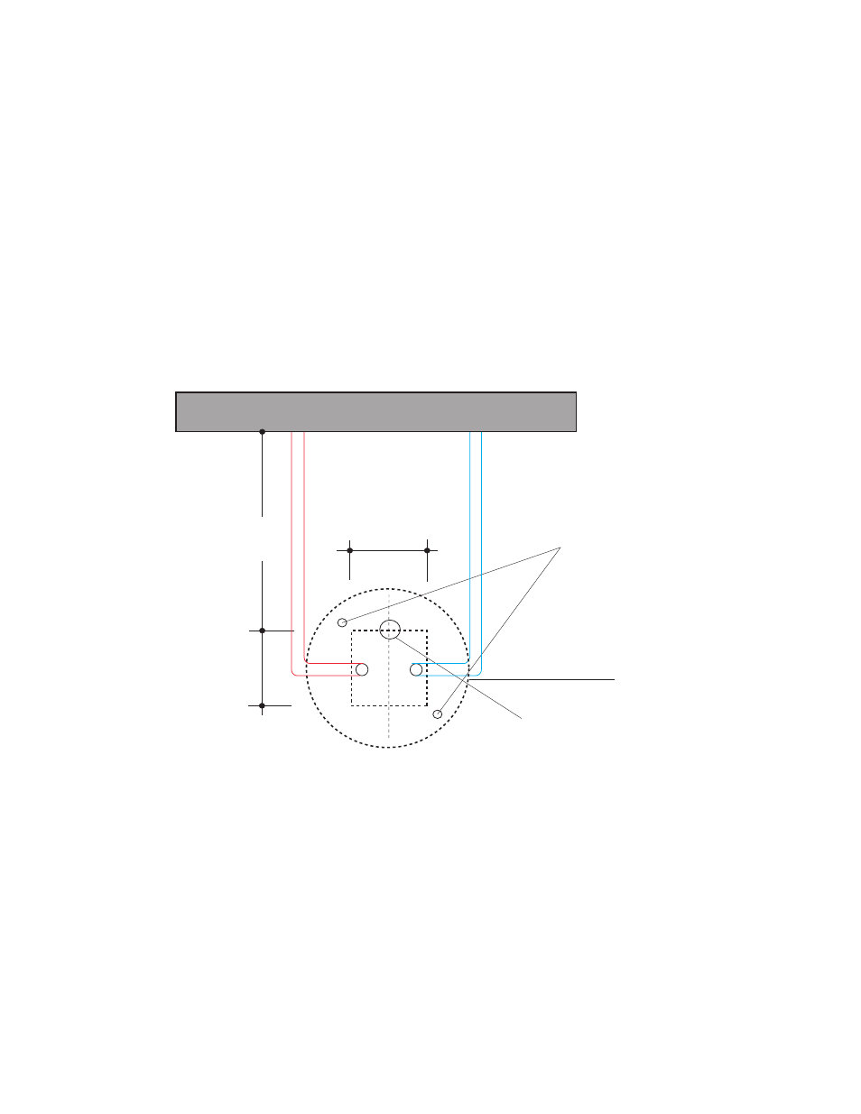
4 3/4"
120
4 3/4"
120
1 1/2” drain outlet raised
12“ above the floor
1. Trace the bottom layout on the floor
where the pedestal is to be placed
(As shown in Fig. 1)
2. Prepare in-floor 1 1/2” drain outlet with
a PVC pipe sticking 12” above the finished
floor. Add 1 1/4” p-trap adapter.
*Water supply (hot and cold) only if needed for deck-mount faucet, needs to be prepared
after consulting with the faucet being installed. In most cases, 3/8” compression valves are
expected. The water supplies should also be raised 10-12” above the floor.
Fig. 1
2 x screws to the floor
(not supplied)
H* C*
FLOOR ROUGH-IN LAYOUT
FRONT
BACK
Min.
9 1/2"
240
wall/fixed obstructions
Bottom of the pedestal
diam. 10” (255mm)
See also other documents in the category Lacava For Home:
- 4558 (10 pages)
- 4288 (11 pages)
- 2895 (9 pages)
- 2895 (10 pages)
- 1495 (9 pages)
- 0112 (9 pages)
- 2982 (7 pages)
- DE200 (10 pages)
- 1595 (10 pages)
- 6972 (9 pages)
- 0140SP (10 pages)
- 5054-42A (8 pages)
- 4500P (1 page)
- 0640 (10 pages)
- EX11 (9 pages)
- 4500G (7 pages)
- 12340 (8 pages)
- TUB07 (6 pages)
- 13010 (8 pages)
- 0475 (10 pages)
- EX03 (11 pages)
- W1001 (8 pages)
- TUB04 (9 pages)
- W1010 (8 pages)
- W1001H1 (8 pages)
- W1030 (9 pages)
- W1065 (9 pages)
- 0142 (9 pages)
- 2840 (9 pages)
- 0142 (9 pages)
- 0142 (9 pages)
- 0142 (9 pages)
- 2840 (9 pages)
- 1910 (10 pages)
- 2840 (9 pages)
- 1460 (9 pages)
- 2860 (9 pages)
- 0660 (9 pages)
- 0621 (8 pages)
- 0620 (8 pages)
- 1414 (9 pages)
- 0470 (9 pages)
- 0146 (9 pages)
- 1420 (8 pages)