Safety lock – Kussmaul Electronics 091-148-12 User Manual
Page 2
January 20, 2002
K U S S M A U L E L E C T R O N IC S C O M P A N Y , IN C .
631-567-5826,
FAX:
631-567-0314,
TEL:
170 CHERRY AVENUE, WEST SAYVILLE, NEW YORK, 11796-1221 USA
SINCE 1967, DESIGNERS OF INNOVATIVE PRODUCTS
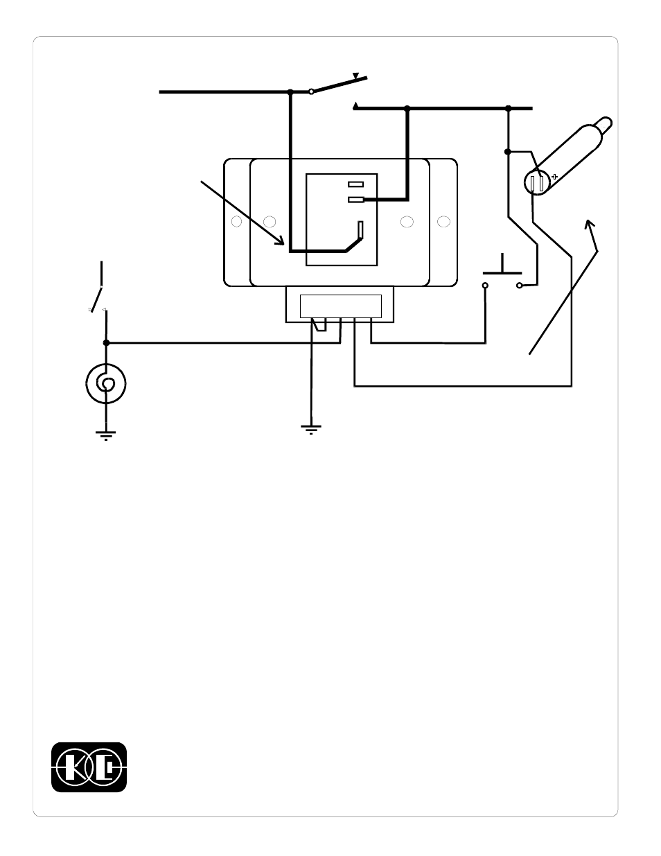
N.O.
COM.
N.C.
1 2 3 4 5
To Ignition
System
IGNITION SWITCH
+12 volt
Power
Brake
Light
+12 V
Brake
Light
Switch
This line resets
SET
PUSHBUTTON
LE
D
In
di
ca
to
r
MODEL 091-148-12
INSTALLATION AND WIRING INSTRUCTIONS
INSTALLATION:
1.
Mount unit in a suitable location protected from moisture and excessive heat.
2. Wire in accordance with the wiring diagram above
OPERATION:
1. With the engine running depress the momentary SET switch S1. The relay will close, the LED will be
illuminated and the engine will continue to run when the key is removed.
2. Remove the key from the ignition. The LED will continue to be illuminated and the engine will continue
to run.
3. Step on the foot brake. The LED will go out and the engine will stop.
4. Start the engine and repeat step 1.
5. Insert the key, turn ignition switch to ON and verify that the engine continues to run when the brake
pedal is depressed.
S1
This line sets
(bypasses ignition)
Indicator illuminates when ignition
switch is bypassed
SAFETY LOCK
A Controller To Permit Engine Operation With The Ignition Switch Removed
The common terminal of the
relay must be connected to
the +12 volt power for the
unit to operate
(OPTIONAL)
OB
SE
R
VE
POL
AR
IT
Y
W
H
EN
IN
ST
AL
LI
N
G