Kussmaul Electronics 091-20WP-120 User Manual
Page 3
INSTALLATION INSTRUCTIONS
1. Locate a convenient place on the vehicle to mount the AUTO EJECT. A minimum clearance
of 4” behind the mounting panel is required as well as 3 3/4” below the center line to clear the
ejection mechanism.
2. Place the template in position and center punch in 7 places.
3a. Drill 2 holes, 1/2” diameter. IMPORTANT THESE HOLES MUST BE DRILLED FIRST.
3b. Drill 4 mounting holes, 3/16” diameter and one, 2 1/4” clearance hole for the AUTO EJECT.
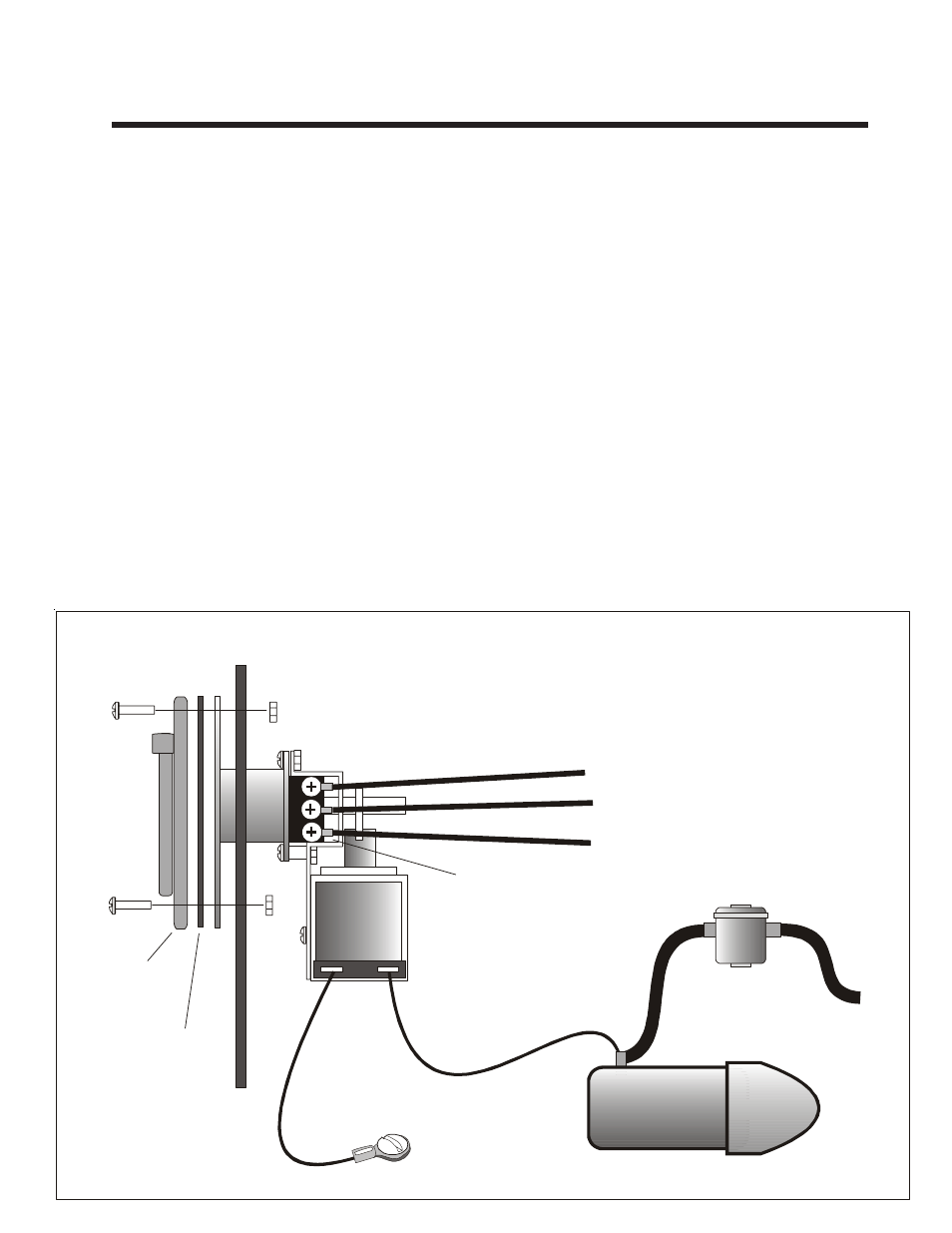
4. Connect one terminal of the solenoid on the AUTO EJECT to the vehicle ground and the other
solenoid terminal to the vehicle’s starter. USE #16 GAUGE WIRE OR HEAVIER.
5. Crimp the ring lugs on the wire and connect the Green, Black, and White power wires to the
accessories on the vehicle.
6. Test installation by installing mating connector into the AUTO EJECT. Energizing the starter
should energize the solenoid and eject the connector.
7. Keep connector and contacts of the AUTO EJECT clean. Clean contacts with WD-40 solvent
as required. Lubricate contacts monthly with “vaseline” to insure free operation.
NOTE: USE ONLY CORD CONNECTOR SUPPLIED WITH THE AUTO EJECT
All connectors are not identical, using a substitue may result in unreliable
operation or failure of the AUTO EJECT to operate.
Chassis
Ground
Solenoid
Vehicle Starter
To Battery
Ground
Line
Neutral
Green
Black
White
Ring lugs supplied
Note: use 12 gauge wire for 20 amps
and 14 gauge wire for 15 amps.
Truck Wall
Gasket
Weather
Proof Cover
#8 Hex Nut
#8 Screw
Note: The Auto Eject is on the
outside of the truck wall.