Installation wiring diagram, Figure 1 – Kussmaul Electronics 091-165-12-DV User Manual
Page 3
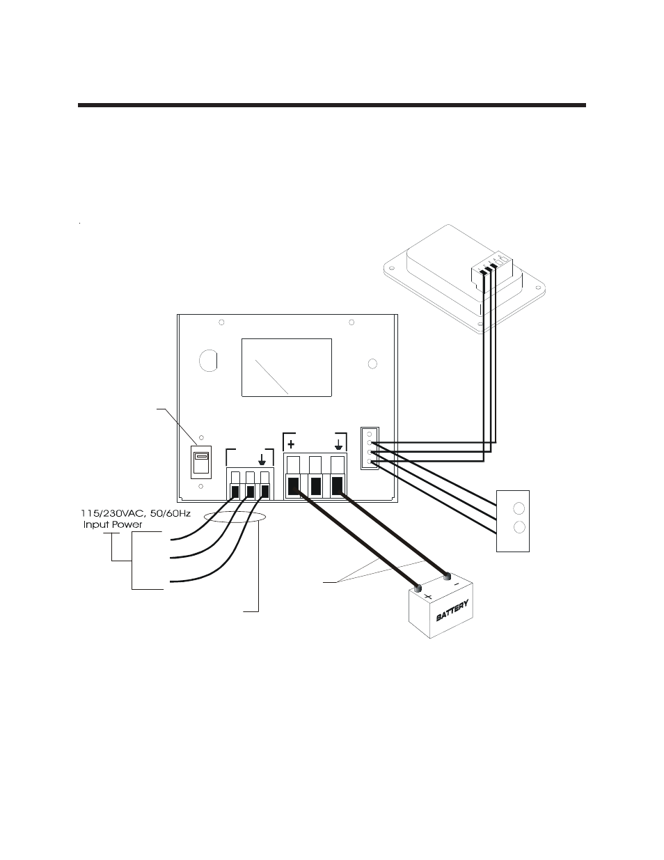
INSTALLATION WIRING DIAGRAM
FUSE
5 AMP
POWER
INPUT
OUTPUT
L N
REMOTE
Line
Neutral
Ground
Optional Economy
Indicator
Optional Bar-graph
Indicator
091-165-016
091-90-012-12
YELLO
W
RED
BLAC
K
AWG 16 X 3
TYPE SJ
AWG 14
NOTE 1
NOTE 1, 2
115V
Notes:
1. 115/230VAC Input Power and Charger Output Power strain relief cover not shown
for clarity. Refer to INSTALLATION "Important Safety Instructions" section of this
manual.
2. Charger output power connections, AWG 14, for 20 feet Maximum. Consult factory
if longer length is required.
3. 115VAC operation shown. For 230VAC toggle voltage select switch down so that
"230V" is clearly shown in window of selector switch.
115/230VAC
SELECTOR SWITCH
115VAC SHOWN
Note 3.
FIGURE 1
This manual is related to the following products: