Installation wiring diagram, Wire size chart – Kussmaul Electronics 091-12VHO-24 User Manual
Page 3
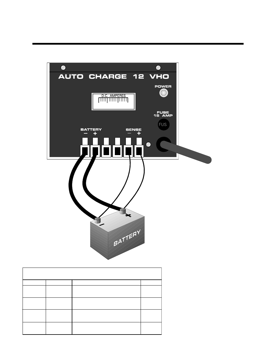
INSTALLATION WIRING DIAGRAM
WIRE SIZE CHART
CONNECTION
ITEM
DEFINITION
WIRE SIZE
BAT-
BATTERY
NEGATIVE
NEGATIVE CHARGING LEAD
FOR BATTERIES
10 AWG
BAT+
BATTERY
POSITIVE
POSITIVE CHARGING LEAD
FOR BATTERY # 1
10 AWG
SENSE
-
NEGATIVE
SENSE
NEGATIVE VOLTAGE SENSE
LEAD. DETECTS VOLTAGE
16 AWG
SENSE
+
POSITIVE
SENSE
POSITIVE VOLTAGE SENSE
LEAD. DETECTS VOLTAGE
16 AWG
NOTE: The sense leads must be
connected to the battery system as shown
for the charger to operate. A simple
check can be made as follows see
example:
EXAMPLE: Assuming a 24 VDC battery
system, the positive sense lead must
read approximately +24 VDC with respect
to the negative sense lead at the charger.
The battery “+” terminal must read
approximately +24 VDC with respect to
the battery “-” terminal at the charger.
These measurements shall be made
before the AC power to the charger is
applied.
IMPORTANT: Each lead wire shall not be
greater than 20 feet for the charger to
deliver the full 20 amp output. If wiring is
to be longer, consult the factory for addi-
tional information.