Kleenmaid RHSGSPOT User Manual
Page 14
18
If the rangehood is to be used in ducting version, the other end
of the pipe must be connected to a device expelling the fumes
to the outside. If the rangehood is to be used in filter version,
then fix the deflector "F" to the chimney support bracket "G"
and connect the other extremity of the pipe to the connection
ring placed on the deflector "F".
19. Make the electrical connections.
20. Apply the chimney stacks and fasten them at the top to the
chimney support "G“ (20b) using 2 screws (20a).
Only for model with optical fibers point lighting (Fig. 1G - 6G):
Check that the chimneys may be removed to permit access to
the optical fibers lamp housing area.
21. Slide the bottom section of the chimney down until it completely
covers the suction unit and slots into the housing provided on top
of the rangehood.
22. Fix the lower section of the chimney with two screws (only for
the model in Fig. 1H/6H-1J/6J).
Replace the grease filter/s and check that the rangehood is
operating correctly.
Electrical connection
The electrical tension must correspond to the tension noted on the
label placed inside the rangehood. Connect the electrical plug,
where provided, to the an easily accessible outlet in conformity with
local standards in force.
Where an electrical plug is not provided (for direct connection to
electrical network) place a standards approved bipolar switch with
an aperture distance of not less than 3mm (accessible) from the
contacts.
Description of the Rangehood - Fig. 1
1 Control panel
2 Grease filter
3 Grease filter release handle
4 lamp
5 Vapour screen
6 Telescopic chimney
7 Air outlet (used for filter version only)
8 point lighting (only for the model in Fig. 1G)
Operation –
All Rangehood versions
Use the high suction speed in cases of concentrated kitchen
vapours. It is recommended that the rangehood suction is switched
on for 5 minutes prior to cooking and to leave in operation during
cooking and for another 15 minutes approximately after terminating
cooking.
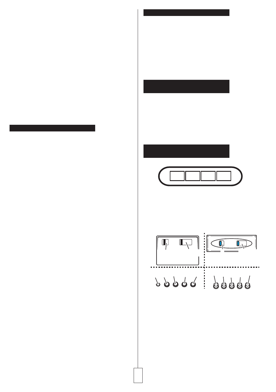
Operation –
Model with button panel
A.
on/off light switch
B.
on/off aspiration switch and minimum power selection
B+C. medium power selection aspiration switch
B+D. maximum power selection aspiration switch
a. ON/OFF lighting
b. OFF motors
c. - d. - e. Minimum suction power (c.), medium (d.), maximum (e.).
f. Operation warning light (where present).
A
B
C
D
a
a b-c d e
f
b-c-d-e
b-c-d-e
a
a b c d e