Accessories, V/a meter unit msd 1, Cooling unit functions in kempomig 4000wr – Kemppi Kempomig 4000R User Manual
Page 8
8 KEMPOMIG 4000R, 4000WR - 0409
© COPYRIGHT KEMPPI OY
KEMPOMIG 4000R, 4000WR - 0409 9
© COPYRIGHT KEMPPI OY
4.
ACCESSORIES
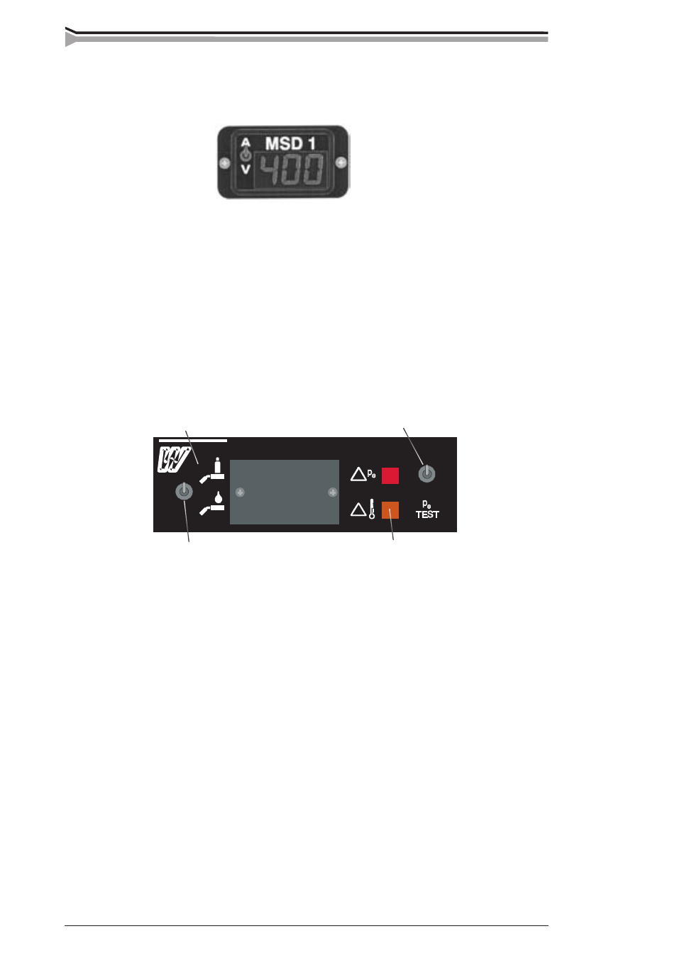
4.1. V/A METER UNIT MSD 1
The V/A meter unit MSD 1 displays during welding true value of welding current or welding
voltage. The current / voltage display is selected with selecting switch of the MSD 1.
For the mounting of the MSD 1, remove the cover plate on the front panel of the unit. The connector
of flat cable fastened to the cover plate is connected to the corresponding connector of MSD 1.
Note! MSD 1 does not display arc voltage but the machine´s pole voltage. Note that due to cable
losses, the arc voltage can be many volts lower than the machine´s pole voltage.
4.2. COOLING UNIT FUNCTIONS IN KEMPOMIG 4000WR
Kempomig 4000WR has an inbuilt cooling unit inside the power source. Operation control switches
of the cooling unit are on the front panel of the power source and the water tank of the cooling
system is in front wall drawer.
Signal lamp for lacking water pressure
Test for water circulation
Selecting switch for gun´s cooling mode
Signal lamp for overheating
4.2.1. Installation of cooling
1. Connect water hoses of the interconnection cable coming from the wire feeder to snap
connectors on the power source´s rear wall. The interconnection cable´s hose marked with
blue colour is for water supplied from the cooling unit to gun. The hose marked with red is for
water returning back from gun to cooling unit. Before connecting the interconnection cable,
check that in hoses there is no dirt, metal powder, rubber waste etc.
2. The cooling unit´s tank is filled with 20 - 40 % glycol / water mixture according to antifreeze
requirements. Instead of glycol / water mixture you can also use another suitable liquid
according to your experience.
3. Set the selecting switch for gun´s cooling mode on the front wall to water cooling mode and
start the power source from the main switch.
4. Press the test switch for water circulation until the signal lamp for water pressure is switched
off. Fill the water hoses for interconnection cable and gun with the test switch in question.
Check the return flow and the tank´s water line. The tank volume is ca. 3 litres, the volume for
gun and interconnection cable is 0.3 – 1.5 litres. Filling of hoses takes 5 s - 3 min.
5. Start welding in a normal way and the pump starts automatically. After the weld end the pump
is still operating for ca. 5-7 min.
If the water does not start circulating, see paragraph for Operation disturbances.
Do not let any waste or dirt get into the water circulation! Check the filling volume before
you start welding!
Use a cooling liquid according to recommendations or one you know to be good. Keep an eye
on liquid material´s quality and possible sediments in hoses and in gun.