Operation and use controls, Welding and return current cables – Kemppi Kempomig 4000R User Manual
Page 5
4 KEMPOMIG 4000R, 4000WR - 0409
© COPYRIGHT KEMPPI OY
KEMPOMIG 4000R, 4000WR - 0409 5
© COPYRIGHT KEMPPI OY
2.4. WELDING AND RETURN CURRENT CABLES
Use only copper cables with cross-sectional area of at least 50 mm
2
.
Table below shows typical loading capacities of rubber insulated copper cables, when ambient
temperature is 25°C and conductor temperature is 85°C.
Cable
Duty cycle ED
Voltage loss / 10 m
100 %
60 %
30 %
50 mm
2
285 A
370 A
520 A
0,35 V / 100 A
70 mm
2
355 A
460 A
650 A
0,25 V / 100 A
95 mm
2
430 A
560 A
790 A
0,18 V / 100 A
To avoid voltage losses and heating, do not overload welding cables over permissible
values.
Fasten the earth clamp of the return current cable carefully, preferably directly onto the work piece.
The contact surface area of the clamp should always be as large and steady as possible. Clean the
contact surface from paint and rust.
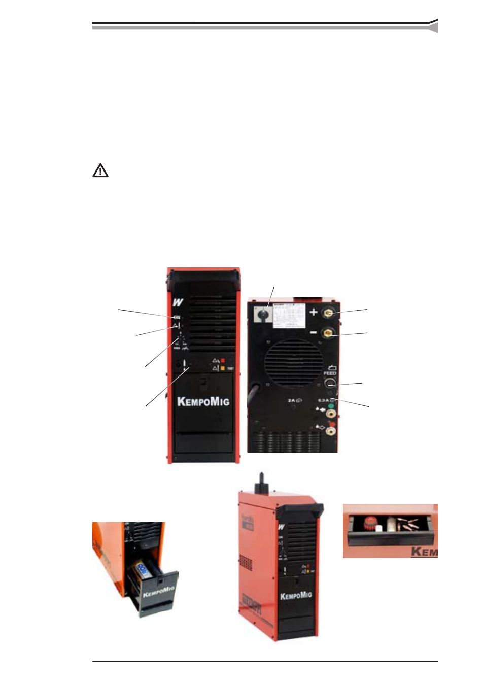
3.
OPERATION AND USE CONTROLS
Kempomig 4000R
Signal lamp for main
switch
Signal lamp for
thermal protection
release
Main switch
Welding current connector (+)
Return current connector (–)
Adjustment for
MMA welding
dynamics *)
Mounting place
for V/A meter unit
MSD1
Control connector
for wire feeder unit
Fuse for control
connector (6,3 A)
Accessory drawer
Accessory drawer